


OM-486 Page 16
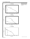
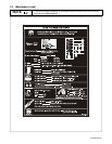
4-7. Selecting Weld Cable Sizes
Total Cable (Copper) Length In Weld Circuit Not Exceeding
Welding
Amperes
100 ft (30 m) Or Less
150 ft
(45 m)
200 ft
(60 m)
250 ft
(70 m)
300 ft
(90 m)
350 ft
(105 m)
400 ft
(120 m)
Amperes
10 – 60%
Duty Cycle
60 – 100% Duty
Cycle
10 – 100% Duty Cycle
100 4 4 4 3 2 1 1/0 1/0
150 3 3 2 1 1/0 2/0 3/0 3/0
200 3 2 1 1/0 2/0 3/0 4/0 4/0
250 2 1 1/0 2/0 3/0 4/0 2-2/0 2-2/0
300 1 1/0 2/0 3/0 4/0 2-2/0 2-3/0 2-3/0
350 1/0 2/0 3/0 4/0 2-2/0 2-3/0 2-3/0 2-4/0
*Weld cable size (AWG) is based on either a 4 volts or less drop or a current density of at least 300 circular mils per ampere. Contact your
distributor for the mm
2
equivalent weld cable sizes. S-0007-E
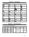
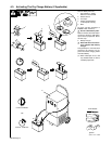
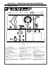
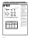
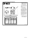
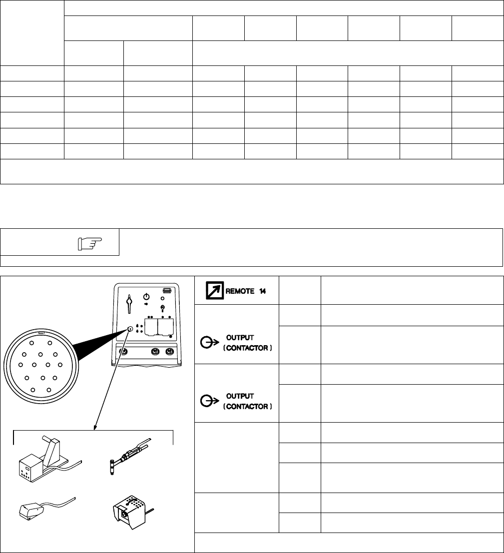
4-8. Remote 14 Receptacle Information
Engine runs at weld/power speed whenever a device connected to the remote 14
receptacle is running.
NOTE
Socket* Socket Information
A 24 volts ac.
AJ
B
K
I
24 VOLTS AC
B Contact closure to A completes 24 volt ac contac-
tor control circuit. Protected by circuit breaker
CB5.
C
L
NH
M
I 115 volts ac.
D
M
G
E
F
115 VOLTS AC
J Contact closure to I completes 115 volt ac contac-
tor control circuit. Protected by circuit breaker
CB6.
C 0 to +10 volts dc output to remote control.
A/V
D Remote control circuit common.
AMPERAGE
VOLTAGE
E 0 to +10 volts dc input command signal from
remote control.
G Circuit common for 24 and 115 volt ac circuits.
ST-801 943-B
GND
K Chassis common.
*The remaining sockets are not used.