


OM-486 Page 13
SECTION 4 – INSTALLATION
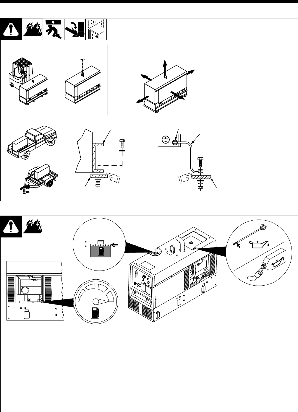
install1 12/99 – Ref. ST-800 652 / Ref. ST-800 477-A / ST-158 936-A / S-0854
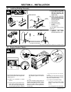
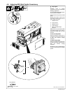
Y Do not weld on base. Weld-
ing on base can cause fuel
tank fire or explosion. Bolt
unit down using holes pro-
vided in base.
Y Always ground generator
frame to vehicle frame to pre-
vent electric shock and static
electricity hazards.
1 Generator Base
2 Metal Vehicle Frame
3 Equipment Grounding
Terminal
4 Grounding Cable
Use #10 AWG or larger insulated
copper wire.
Y If unit does not have GFCI re-
ceptacles, use GFCI-
protected extension cord.
1
2
Electrically bond genera-
tor frame to vehicle frame
by metal-to-metal contact.
GND/PE
3
4
2
OR
OR
18 in
(460 mm)
18 in
(460 mm)
18 in
(460 mm)
18 in
(460 mm)
18 in
(460 mm)
OR
Movement Airflow Clearance
Location
Grounding
Y Do not lift unit from end.
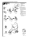
4-1. Installing Welding Generator
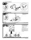
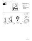
4-2. Engine Prestart Checks
Ref. ST-151 983 / ST-801 942-C / Ref. ST-800 395
1/2 in
(13 mm)
Full
Gasoline
Full
Check all fluids daily. Engine must be cold
and on a level surface. Unit is shipped with
10W30 engine oil.
. Follow run-in procedure in engine
manual.
. This unit has a low oil pressure shut-
down switch. However, some condi-
tions may cause engine damage be-
fore the engine shuts down. Check oil
level often and do not use the oil pres-
sure shutdown system to monitor oil
level.
1 Fuel
Add fresh fuel before starting engine the
first time (see maintenance label for specifi-
cations). Fill fuel tank up to 1/2 in. (13 mm)
from top to allow room for expansion.
Check fuel level on a cold engine before
use each day.
2 Oil
After fueling, check oil with unit on level sur-
face. If oil is not up to full mark on dipstick,
add oil (see maintenance label).
. To improve cold weather starting:
Keep battery in good condition. Store
battery in warm area off concrete
surface.
Use correct grade oil for cold weather.