


OM-221 694 Page 13
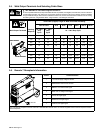
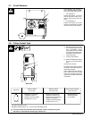
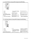
3-7. Circuit Breakers
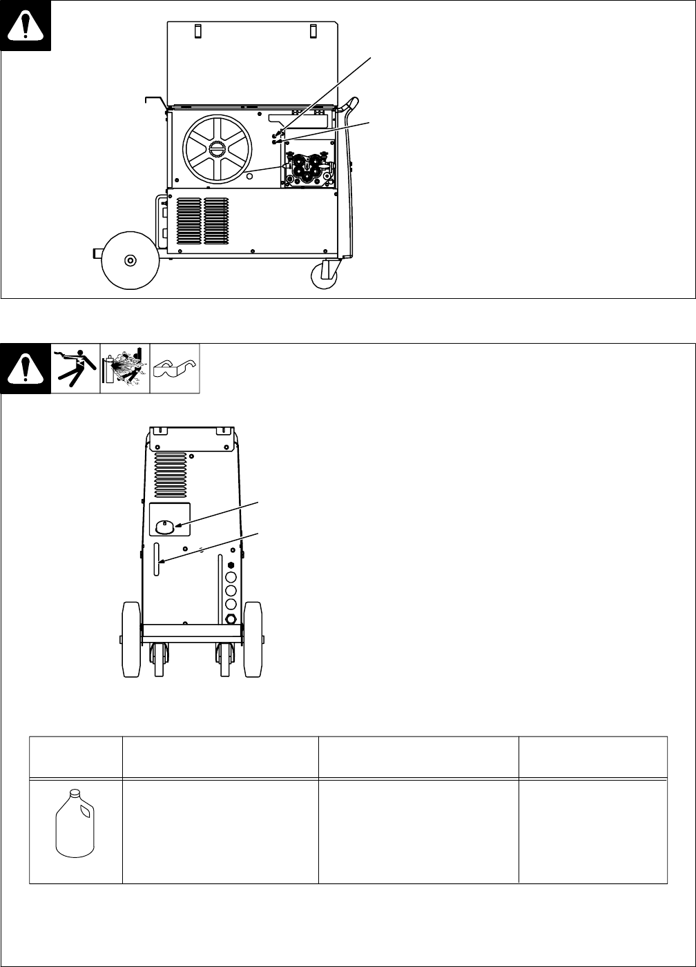
Circuit breakers with numbers 7
and 10 are placed inside the welder
on the wire feeder side as shown.
1 Circuit Breaker 7
Protects the auxiliary 115 volt AC
used for the water cooling unit in-
side the power source, from over-
load.
2 Circuit Breaker 10
Protects the auxiliary 24 volt AC
used for the wire feeder unit inside
the power source, from overload.
1
2
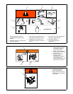
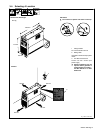
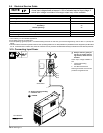
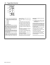
3-8. Filling Coolant Tank
. Operating cooler when coolant
is low can damage cooler and
torch components. Always
have proper amount of coolant
in tank and use coolant recom-
mended by the manufacturer.
1 Coolant Tank Cap
2 Coolant Level Indicator
. Remove shielding gas cylinder
from rear of unit to fill coolant
tank.
Unscrew cap from tank.
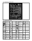
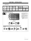
Use table to select proper coolant,
and fill tank until coolant appears in
upper half of indicator.
Check coolant level after attaching
torch coolant hoses and running
cooler. Be sure coolant appears in
upper half of indicator. Add coolant
if necessary.
Rear View
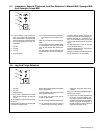
MILLER Low Conductivity
Coolant No. 043 810**;
Distilled Or Deionized Water
OK Above 32° F (0° C)
MILLER Low Conductivity
Coolant No. 043 810**; Or
MILLER Aluminum Protecting
Coolant No. 043 809**;
Distilled Or Deionized Water
OK Above 32° F (0° C)
GTAW Or Where
HF* Is Used
GMAW Or Where
HF* Is Not Used
Application
*HF: High Frequency Current
**MILLER coolants protect to -37° F (-38°C) and resist algae growth.
Coolant
MILLER Aluminum
Protecting Coolant
No. 043 809**
Where Coolant Contacts
Aluminum Parts
Y Use of any coolant other than those listed in the table voids the warranty on any parts
that come in contact with the coolant (pump, radiator, etc.).
1
2