


OM-221 694 Page 15
SECTION 4 − OPERATION
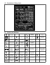
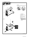
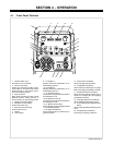
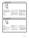
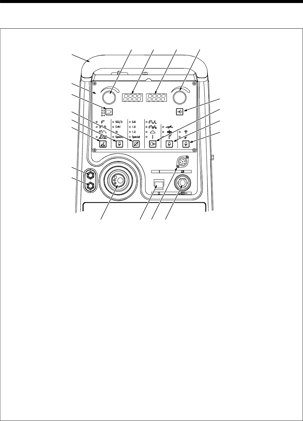
4-1. Front Panel Controls
14
20
18
19
1210911
7
8
5
6
17
13
16
15
2 1 4 3
1 ON/OFF Switch (I/O)
Use switch to turn unit On/Off.
2 MIG Gun Connector
Positive gun connection for MIG or elec-
trode holder for Stick Electrode Positive
welding process, or work clamp connec-
tion for TIG welding process.
3 Work Connector
Work clamp connection for MIG or Stick
Electrode Positive welding process, or
torch connection for TIG welding process.
4 Remote Control Receptacle
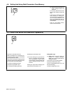
5 Red Quick Connect Fitting
Coolant return from torch.
6 Blue Quick Connect Fitting
Coolant output to torch.
7 Handle
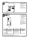
8 Control Panel
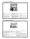
9 D1 (Display 1)
Displays values and parameters for se-
lected welding process.
10 D2 (Display 2)
Displays values and parameters for se-
lected welding process.
11 E1 (Encoder Control 1)
Use control to change values and parame-
ters that appear on D1.
12 E2 (Encoder Control 2)
Use control to change values and parame-
ters that appear on D2.
13 P1 (Memory Push Button)
Allows selecting program storage locations
1-4 as indicated by LED’s.
14 P2 (Setup Push Button)
Allows selecting setup or advanced pro-
gramming menus.
15 P3 (Process Push Button)
Allows selecting welding process.
16 P4 (Material Push Button)
Allows selecting material type for synergic
MIG and synergic pulsed MIG processes.
17 P5 (Wire Diameter Push Button)
Allows selecting desired welding wire di-
ameter for synergic MIG and synergic
pulsed MIG processes.
18 P6 (Trigger Selection Push Button)
Allows selecting desired trigger mode.
19 P7 (Inductance/Thickness/Gas Push
Button
Allows selecting additional welding param-
eters.
20 P8 (Jog/Purge Push Button)
Performs jog and purge operations.