


6 7
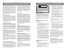
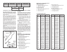
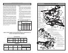
Max Height
at 45°
6.55" H at
.40" W
Capacities
Max Height
at 90°
6.55" H at
2.10" W
Max Width
at 90°
13.5" W at
4.02" H
Max Width
at 45°
9.51" W at
4.02" H
Miter Cuts
Compound Cuts
45° Miter and 45° Bevel
Left Bevel
9.51" W at
2.25" H
Right Bevel
9.51" W at
1.9" H
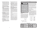
No Load
RPM
3 200
Volts
AC
120
Cat.
No.
6955-20
Specifi cations
Amps
15
Arbor
Size
5/8"
Blade
Size
12"
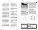
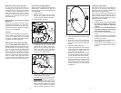
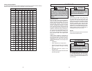
Grounded tools require a three wire exten-
sion cord. Double insulated tools can use
either a two or three wire extension cord.
As the distance from the supply outlet
increases, you must use a heavier gauge
extension cord. Using extension cords with
inadequately sized wire causes a serious
drop in voltage, resulting in loss of power
and possible tool damage. Refer to the table
shown to determine the required minimum
wire size.
The smaller the gauge number of the wire,
the greater the capacity of the cord. For ex-
ample, a 14 gauge cord can carry a higher
current than a 16 gauge cord. When using
more than one extension cord to make up
the total length, be sure each cord contains
at least the minimum wire size required. If
you are using one extension cord for more
than one tool, add the nameplate amperes
and use the sum to determine the required
minimum wire size.
Guidelines for Using Extension Cords
• If you are using an extension cord out-
doors, be sure it is marked with the suffi x
“W-A” (“W” in Canada) to indicate that it
is acceptable for outdoor use.
• Be sure your extension cord is prop-
erly wired and in good electrical
condition. Always replace a damaged
extension cord or have it repaired by a
qualifi ed person before using it.
• Protect your extension cords from sharp
objects, excessive heat and
damp or wet areas.
READ AND SAVE ALL INSTRUCTIONS FOR FUTURE USE.
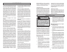
Recommended Minimum Wire Gauge
for Extension Cords*
Extension Cord Length
* Based on limiting the line voltage drop to
fi ve volts at 150% of the rated amperes.
Nameplate
Amperes
0 - 2.0
2.1 - 3.4
3.5 - 5.0
5.1 - 7.0
7.1 - 12.0
12.1 - 16.0
16.1 - 20.0
25'
18
18
18
18
16
14
12
75'
18
18
16
14
12
10
100'
18
16
14
12
10
150'
16
14
12
12
50'
18
18
18
16
14
12
10
EXTENSION CORDS
Weight
65 lbs
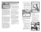
AL
WA
Y
S
SECURE
GUAR
D
B
R
ACKET
WITH
BOTH
SCREWS
AFTER
BLAD
E
C
HANGE
.
T
OUJOURS
F
I
XE
R
LE
SUPPOR
TD
E
DISPOSITI
FD
E
PROTECTION
À
L'AIDE
DE
S
DEUX
VI
SA
P
RÈSAV
OIR
CHANG
ÉL
AL
AME.
SIEM
PR
ES
E
D
EBE
A
F
I
A
N
Z
A
R
E
L
S
O
PO
R
T
E
T
O
RCON
AMBO
S
WA
R
N
I
N
G
AV
E
RT
I
S
S
E
M
E
N
T
A
D
VE
RT
E
NC
I
A
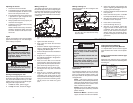
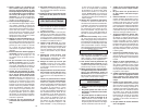
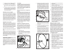
FUNCTIONAL DESCRIPTION
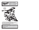
1. Saw head
2. Light on/off switch
3 On/Off trigger
4. Upper guard
5. Lower guard
6. Guard bracket
7. Lights
8. Fence
9. Turntable
10. Digital miter
angle readout
11. Fine adjustment
ring
12. Miter angle
lock knob
13. Detent lever
14. Adjustable kerf
plates
15. Miter angle pointer
16. Miter angle scale
8
5
4
1
16
15
26
8
18
14
11
21
23
19
7
6
17
25
13
12
9
20
10
22
27
2
3
31
29
32
28
30
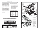
17. Mounting holes (4)
18. Fence lock knob
19. Face board mounting
holes (4)
20. Slide rails
21. Bevel angle scale
22. Depth stop paw
23. Head lock-down pin
24. Dust ejection port
25. Dust chute
26. Bevel adjustment
lever
27. Depth stop adjust-
ment knob
28. Spindle lock
29. Dust elbow (Dust bag
not shown)
30. Slide rail lock
31. Wrench storage
32. Carrying handles
24