


10 11
Raising and Lowering the Saw Head
The saw head must be locked down for
transporting and storing the tool. The tool
is shipped with the saw head locked down.
To unlock it, press and hold down the saw
head and simultaneously pull out the lock
down pin. To lock the saw head, press and
hold down the saw head and then push in
the lock down pin.
Locking and Unlocking the Sliding
Mechanism
Always lock the sliding mechanism before
transporting or storing the saw. To unlock it,
loosen the slide rail lock by turning it coun-
terclockwise. To lock it, tighten the slide rail
lock by turning it clockwise.
Lock-Off
There is a hole in the trigger through which a
padlock will fi t to lock the tool when it is not
in use. Use a padlock with a 1/4" shackle
and always unplug the tool before installing
it (padlock not supplied with tool).
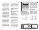
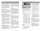
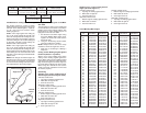
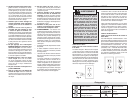
Selecting the Correct Miter Saw Blade
Use only sliding miter saw blades with the
MILWAUKEE Sliding Dual Bevel Miter Saw.
Saw blades with a 0° hook angle or a nega-
tive hook angle work well for Sliding Miter
saws. A negative hook angle means that
teeth tip away from the direction of rotation,
and a 0° degree hook angle means that the
teeth are in line with the center of the blade.
A low or negative hook angle will slow the
feed rate and will also minimize the blade’s
tendency to “climb” the material being cut.
Fig. 1
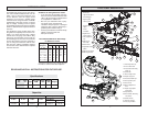
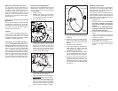
Installing and Changing Blades
Always use clean, sharp blades because dull
blades tend to overload the tool, bind and
cause pinching. Use only 12" blades rated at
least 5500 RPM.
1. Unplug the tool.
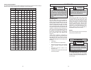
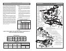
2. With the saw head up, use the wrench
to loosen the guard bracket rear screw
1/4 turn using the wrench provided (1).
3. Raise the lower guard (2).
Loosen guard
bracket rear
screw
Rotate lower
guard up
1
2
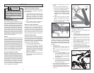
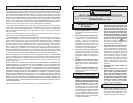
4. Loosen (do not remove) the guard
bracket front screw (3) until the guard
bracket can be raised to expose the
blade screw (4). Lower the lower guard
until it rests on the guard bracket front
screw. This will hold it up and out of the
way during the blade change.
Fig. 2
Loosen guard
bracket
front screw
3
4
Rotate guard
bracket up
5. Press in the spindle lock and rotate the
spindle until the lock engages.
6. Use the wrench to loosen and remove the
left-hand thread blade screw clockwise.
7. Remove the outer blade fl ange, blade,
blade washer, and inner blade fl ange.
Wipe the fl anges, washer, and spindle
to remove dust and debris. Inspect the
parts for damage. Replace if needed.
Adjusting the Kerf Plates
Kerf plates reduce tear-out and splintering
along the cut by providing edge support.
Because blades vary in width, adjust the kerf
plates with every blade change.
Never make a cut without the adjustable kerf
plates installed. The kerf plates can be set
at their maximum width to accommodate all
blade widths and bevel angles if tear-out and
splintering are not a concern.
1. Unplug the tool.
2. Install the blade to be used. Each time
the blade is changed, check to be
sure the kerf plates are adjusted
properly.
3. Set the bevel angle. Each time the bevel
is changed, check to be sure the kerf
plates are adjusted properly.
4. Loosen the six kerf plate adjusting
screws.
5. Lower the saw head to the full depth of
cut (the point where the saw head will
not lower any further).
6. Slide the kerf plates to the desired spac-
ing and tighten the six screws.
7. Check to be sure the saw blade does not
contact the kerf plates before starting
the saw.
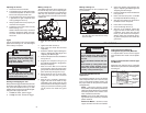
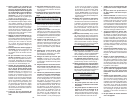
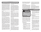
Fig. 3
Outer fl ange
Inner fl ange
Blade
Blade
screw
Blade
washer
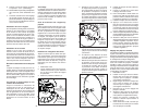
8. Install the inner blade fl ange as shown.
9. Insert the blade washer into the blade
arbor hole.
10. Match the arrow on the blade with the
arrow on the lower guard. Slide the
blade into the upper guard and onto the
spindle.
11. Install the outer blade fl ange.
12. Press in the spindle lock and rotate the
blade until the lock engages. Insert and
securely tighten the blade screw coun-
terclockwise with the wrench.
13. Rotate the guard bracket into position
and securely tighten the two screws. Re-
turn the wrench to the wrench holder.
14. Lower the saw head and check the
clearance between the blade and the
adjustable kerf plates. Important: The
lower guard must move freely. The blade
should rotate freely (see "Adjusting the
Kerf Plates").