


12 13
Using Face Boards
(Zero Clearance Sub Fences)
There are face board mounting holes in the
fences for attaching face boards. Face boards
place distance between the fence and the
workpiece, providing improved support for
some workpieces. Workpiece splintering can
be reduced by using face boards. As the width
of the face board increases, the height of the
workpiece which can be cut increases slightly
(but the width capacity decreases slightly).
Similarly, if you place a face board on the saw
table and place a workpiece on top of the face
board, you can cut a workpiece with greater
width (but with less height).
Guards
The tool is shipped with both the upper and
lower guard installed. The lower guard should
cover the blade when the saw head is up and
it should move freely and open automatically
as the saw head is lowered into the workpiece.
If the lower guard appears loose, sticks, or if
it does not move to cover the blade when the
saw head is up, tighten the guard bracket
screws. If it still does not move freely, take
the saw to an authorized service center for
repairs. Do not attempt to open the guard
further than the automatic action permits.
Select the Workpiece Carefully
Be cautious of pitchy, knotty, wet or warped
workpieces. These materials are likely to cre-
ate pinching conditions. Workpieces that bow
and pinch may result in kick back. Inspect
for and remove nails before cutting. Always
keep blades clean and sharp; otherwise the
blade produces a narrow kerf and is likely
to be pinched by the workpiece. This tool is
not recommended for cutting ferrous metals
such as iron and steel. See Applications for
a more complete list of materials.
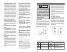
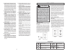
WARNING
To reduce the risk of injury, wear
safety goggles or glasses with side
shields. Always wait for the blade
to stop completely and unplug the
tool before changing accessories or
making adjustments. Do not defeat
the guards.
OPERATION
Support the Workpiece Properly
Always support the workpiece during opera-
tion. Otherwise, the workpiece may pull up
and into the saw.
1. Use the Fence: Align the workpiece fl ush
against the fence to provide a straight
path for the saw blade. This will help
eliminate the tendency for the blade
teeth to bind. The fence can be used as
a support for miter, bevel and compound
cuts.
2. Use a clamp: Clamp the workpiece to
the fence or base with a C-clamp.
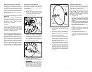
Support of Longer Workpieces
Longer workpieces need support along their
full length. If you are using the saw on a
level work bench, prop up the workpiece to
a height of 4-3/4" from the bottom of the saw
feet. There are also many aftermarket work
tables specifi cally designed for miter saws that
provide supports for all types of workpieces.
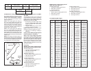
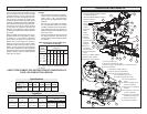
Adjusting the Miter Angle
The miter angle can be set using detents for
commonly cut angles, as well as fi nely adjust-
ed to any angle. Use the miter angle pointer
to adjust the turntable to any whole degree
across the miter range. The digital miter angle
readout shows the selected angle.
1. Loosen the miter angle lock knob.
2. To set the miter angle, pull up on the
detent lever and rotate the turntable
to the detent angle closest to the de-
sired angle. The saw cuts miter angles
from 55° on the left to 60° on the right.
Detents are available at 0°, 15°, 22.5°
32.62°, 45°, and 60°.
3. Tighten the miter angle lock knob to use
the miter angle set at the detent before
making a cut.
Adjusting the Depth of Cut
The depth of the cut can be adjusted for
groove or rabbet cuts.
1. Unplug the tool.
2. To set the depth of cut, swivel the depth
stop paw toward the front of the saw.
3. Lower the saw head to the desired depth
of cut.
4. Rotate the depth stop adjustment knob
until it contacts the paw. Lock in the
depth using the lock nut.
5. Plug in the tool and make a test cut to
verify the depth of cut is correct.
6. To remove the depth of cut limit, loosen
the lock nut by turning counterclockwise
and swivel the paw away from the front
of the saw.
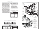
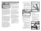
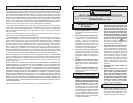
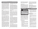
4. To make a fi ne adjustment to the miter
angle:
A. Pull up and hold the detent lever .
B. Push the fi ne adjustment ring forward
until it locks to engage override.
C. Rotate the fi ne adjustment ring left
or right until the desired angle is
displayed on the digital miter angle
readout. ¼ turn = 1° change in miter
angle.
D. Tighten the miter angle lock knob
to secure the table before making a
cut.
E. Pull up on the detent lever to release
the fi ne adjustment ring.
Fig. 4
E
D
C
B
A
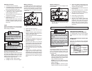
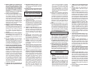
Fig. 5
Detent Angles
Unlock
Lock
Bevel
Adjustment
Lever
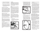
Adjusting the Bevel Angle
The bevel angle can be set using detents for
commonly cut angles, as well as adjusted
to any angle in between by using the bevel
angle scale. The bevel mechanism also has
several degrees of overtravel on both the left
and right.
1. Unplug the tool.
2. To adjust the bevel angle, place one
hand on the front handle for better con-
trol.
3. Using the other hand, lift the bevel ad-
justment lever:
A. To use pre-set detents, lift the
bevel adjustment lever half-way
up (until it "clicks") to move the
saw head left or right, with stops at
pre-set detents.
B. To freely move the head, lift the
bevel adjustment lever all the way
up to freely move the saw head
across the bevel range.
4. Pull or push the saw head to the desired
angle using the bevel angle scale.
5. Lock the bevel angle by pressing down
the bevel adjustment lever before mak-
ing a cut.
Fig. 6
Paw
Knob
Lock nut