


11
2
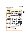
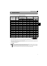
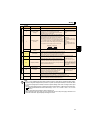
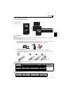
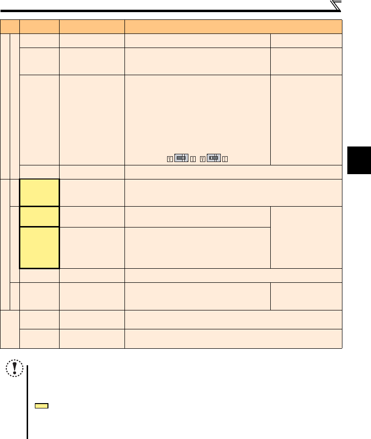
Wiring
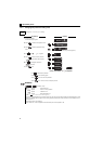
Control circuit/input signal
Frequency setting
10
Frequency setting power
supply
Used as power supply when connecting potentiometer for
frequency setting (speed setting) from outside of the inverter.
5VDC
permissible load current 10mA
2
Frequency setting
(voltage)
Inputting 0 to 5VDC (or 0 to 10V) provides the maximum output
frequency at 5V (10V) and makes input and output
proportional. Use Pr. 73 to switch between input 0 to 5VDC
(initial setting) and 0 to 10VDC input.
Input resistance 10k ± 1k
Permissible maximum voltage
20VDC
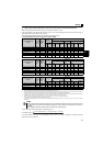
4
Frequency setting
(current)
Inputting 0 to 20mADC (or 0 to 5V / 0 to 10V) provides the
maximum output frequency at 20mA and makes input and
output proportional. This input signal is valid only when the AU
signal is ON (terminal 2 input is invalid). To use terminal 4
(initial setting is current input), set "4" to any of Pr.178 to Pr.184
(input terminal function selection), and turn AU signal ON. Use
Pr. 267 to switch among input 4 to 20mA (initial setting), 0 to
5VDC, and 0 to 10VDC. Set the voltage/current input switch in
the "V" position to select voltage input (0 to 5V/0 to 10V).
Voltage input:
Input resistance 10k ± 1k
Permissible maximum voltage
20VDC
Current input:
Input resistance 233 ± 5
Maximum permissible current
30mA.
5
Frequency setting
common
Common terminal for the frequency setting signals (terminals 2 and 4). Do not earth (ground).
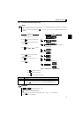
Control circuit/output signal
Relay
A, B, C
Relay output
(fault output)
1 changeover contact output indicates that the inverter fault occurs.
Fault: discontinuity across B and C (continuity across A and C),
Normal: continuity across B and C (discontinuity across A and C)
Contact capacity 230VAC 0.3A (power factor = 0.4) 30VDC 0.3A
Open collector
RUN Inverter running
Switched Low when the inverter output frequency is equal to or
higher than the starting frequency (initial value 0.5Hz).
Switched High during stop or DC injection brake operation.
Permissible load 24VDC
(Maximum 27VDC) 0.1A
(a voltage drop is 3.4V
maximum when the signal is
ON)
Low is when the open
collector output transistor is
ON (conducts). High is when
the transistor is OFF (does
not conduct).
FU Frequency detection
Switched Low when the inverter output frequency is equal to or
higher than the preset detected frequency and High when less
than the preset detected frequency.
SE
Open collector
output common
Common terminal of terminal RUN and FU.
Pulse
FM For meter
Used to output a selected monitored item (such as Output
frequency) among several monitored items. (Not output during
inverter reset.)The output signal is proportional to the
magnitude of the corresponding monitoring item.
Permissible load current 1mA
1440 pulses/s at 60Hz
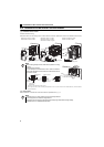
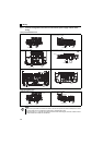
Communication
— PU connector
With the PU connector, RS-485 communication can be established.
· Conforming standard: EIA-485 (RS-485) · Transmission format: Multi-drop link
· Communication speed: 4800 to 38400bps · Overall extension: 500m
— USB connector
A personal computer and an inverter can be connected with a USB (Ver1.1) cable.
· Interface: conforms to USB1.1 · Transmission Speed: 12Mbps
· Connector: USB mini B connector (receptacle mini B type)
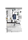
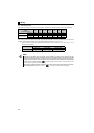
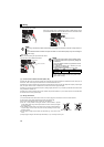
Note
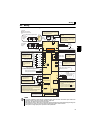
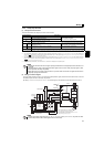
Set Pr. 267 and a voltage/current input switch correctly, then input an analog signal in accordance with the setting.
Applying a voltage with voltage/current input switch in "I" position (current input is selected) or a current with switch
in "V" position (voltage input is selected) could cause component damage of the inverter or analog circuit of output
devices.
The inverter will be damaged if power is applied to the inverter output terminals (U, V, W). Never perform such wiring.
indicates that terminal functions can be selected using Pr. 178 to Pr. 182, Pr. 184 and Pr. 190 to Pr. 192 (I/O terminal
function selection).
Terminal names and terminal functions are those of the factory set.
When connecting the DC power supply, be sure to connect the plus side of the power supply to terminal P/+ and
minus side to terminal N/-. Opposite polarity will damage the inverter.
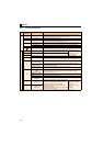
Type
Terminal
Symbol
Terminal Name Description
Voltage input
Current input
(initial status)