


43
Check first when you have a trouble
8
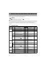
8.3 Check first when you have a trouble
* For further information on troubleshooting, refer to the Instruction Manual (Applied).
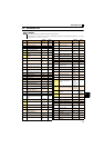
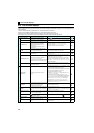
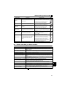
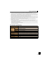
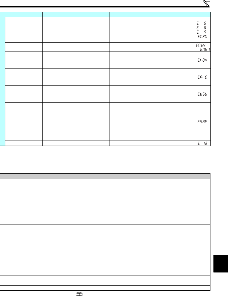
Fault
CPU fault
An error has occurred in the CPU and in the
peripheral circuits.
Take measures against noises if there are devices producing
excess electrical noises around the inverter.
Check the connection between the terminals PC and SD. (E6/
E7)
If the situation does not improve after taking the above
measure, please contact your sales representative.
Brake sequence fault
A sequence error has occurred while the brake
sequence function (Pr.278 to Pr.283) is valid.
Check the parameter setting and check the wiring.
Inrush current limit
circuit fault
The resistor of the inrush current limit circuit has
overheated.
Configure a circuit where frequent power ON/OFF is not
repeated.
If the situation does not improve after taking the above
measure, please contact your sales representative.
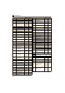
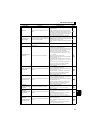
Analog input fault
A voltage (current) has been input to terminal 4
when the setting in Pr. 267 Terminal 4 input selection
and the setting of voltage/current input switch are
different.
Give a frequency command by a current input or set Pr.267
Terminal 4 input selection, and set the voltage/current input switch
to voltage input.
USB communication
fault
The communication has been broken for Pr. 548
USB communication check time interval.
Check the Pr.548 USB communication check time interval setting.
Check the USB communication cable.
Increase the Pr.548 USB communication check time interval
setting, or set "9999."
Safety circuit fault
The safety circuit fault has occurred, or either the
contact between terminals S1 and PC or the
contact between terminals S2 and PC has
opened.
When not using the safety stop function, short across
terminals S1 and PC and across S2 and PC with shorting
wire.
When using the safety stop function, check that wiring of
terminal S1, S2 and PC is correct and the safety stop input
signal source such as safety relay module is operating
properly. Refer to the Safety stop function instruction manual
(BCN-211508-004) for causes and countermeasures. (Refer
to the front cover for how to obtain the manual.)
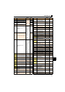
Internal circuit fault An internal circuit fault has occurred. Please contact your sales representative.
Resetting the inverter initializes the internal cumulative heat value of the electronic thermal relay function.
This protective function is not available in the initial status.
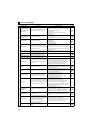
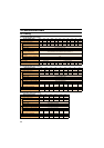
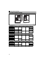
Description Countermeasure
Motor does not start.
Check start and frequency command sources and enter a start command (STF, etc.) and a
frequency command.
Motor or machine is making abnormal
acoustic noise.
Take EMC measures if a steady operation cannot be performed due to EMI. Alternatively, set
the Pr.74 Input filter time constant setting higher.
Inverter generates abnormal noise. Install a fan cover correctly.
Motor generates heat abnormally. Clean the motor fan. Improve the environment.
Motor rotates in the opposite direction.
Connect phase sequence of the output cables (terminal U, V, W) to the motor correctly.
Alternatively, check the connection of the start signal. (STF: forward rotation, STR: reverse
rotation)
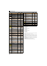
Speed greatly differs from the setting.
Check the settings of Pr.1 Maximum frequency, Pr.2 Minimum frequency, Pr.18 High speed maximum
frequency, and calibration parameters C2 to C7.
Acceleration/deceleration is not smooth. Reduce the load. Alternatively, increase the acceleration/deceleration time.
Speed varies during operation.
Check the frequency setting signals. If the load fluctuates, select Advanced magnetic flux
vector control or General-purpose magnetic flux vector control.
Operation mode is not changed properly.
Turn OFF the start signal (STF or STR). Check if Pr.79 Operation mode selection is set
appropriately.
Operation panel display is not operating. Check the wiring and the installation.
Motor current is large.
Increase/decrease the Pr.0 Torque boost setting value by 0.5% increments so that stall
prevention does not occur. Set the rated motor frequency to Pr.3 Base frequency.
Speed does not accelerate.
Check the settings of Pr.1 Maximum frequency, Pr.2 Minimum frequency, and calibration parameters
C2 to C7. To operate at 120Hz or higher, set Pr.18 High speed maximum frequency.
Unable to write parameter setting. Check Pr.77 Parameter write selection setting.
Function Name Description Corrective action Display
to