


42
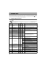
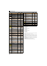
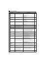
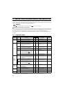
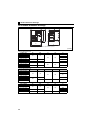
List of fault displays
Fault
Inverter overload trip
(electronic thermal O/L
relay function)
The electronic thermal relay function for inverter
element protection has been activated.
Set the acceleration time longer.
Adjust the Pr. 0 Torque boost setting.
Set the Pr. 14 Load pattern selection setting according to the
load pattern of the using machine.
Reduce the load.
Set the surrounding air temperature to within the
specifications.
Motor overload trip
(electronic thermal O/L
relay function)
The electronic thermal relay function for motor
protection has been activated.
Reduce the load.
For a constant-torque motor, set the constant-torque motor in
Pr. 71 Applied motor.
Set the stall prevention operation level accordingly.
Heatsink overheat The heatsink has overheated.
Set the surrounding air temperature to within the
specifications.
Clean the heatsink.
Replace the cooling fan.
Input phase loss
One of the three phases on the inverter input side
has been lost. It may also appear if phase-to-
phase voltage of the three-phase power input has
become largely unbalanced.
Wire the cables properly.
Repair a break portion in the cable.
Check the Pr. 872 Input phase loss protection selection setting.
Set Pr. 872 Input phase loss protection selection = "0" (without
input phase loss protection) when three-phase input voltage is
largely unbalanced.
Stall prevention stop
The output frequency has dropped to 1Hz as a
result of deceleration due to the excess motor load.
Reduce the load. (Check the Pr. 22 Stall prevention operation level
setting.)
Brake transistor alarm
detection
A fault has occurred in the brake circuit, such as a
brake transistor breakage.(In this case, the
inverter must be powered off immediately.)
Replace the inverter.
Output side earth (ground)
fault overcurrent at start
An earth (ground) fault has occurred on the
inverter's output side (detected only at a start).
Remedy the ground fault portion.
Output phase loss
One of the three phases (U, V, W) on the inverter's
output side (load side) has been lost during
inverter operation.
Wire the cables properly.
If the motor capacity is smaller than the inverter capacity,
choose the inverter and motor capacities that match.
If the motor is coasting, stop the motor, then input a start
command. Alternatively, use the automatic restart after
instantaneous power failure/flying start function.
External thermal relay
operation
The external thermal relay connected to the OH
signal has been activated.
Reduce the load and operate less frequently.
Even if the relay contacts are reset automatically, the inverter
will not restart unless it is reset.
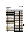
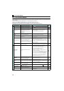
Option fault
A communication option has been mounted while
Pr.296 Password lock level = "0 or 100."
To apply the password lock when installing a communication
option, set Pr.296 Password lock level "0, 100."
If the problem still persists after taking the above measure,
contact your sales representative.
Communication option
fault
A communication error has occurred on the
communication line of the communication option.
Check the settings of the option functions.
Connect the built-in option securely.
Check the connections of the communication cables.
Connect terminating resistors correctly.
Option fault
A fault, such as a contact fault, has occurred at the
contactor of the inverter or the plug-in option. The
setting of the switch on the plug-in option, which is
for manufacturer setting, has been changed.
Connect the plug-in option securely.
Take measures against noises if there are devices producing
excess electrical noises around the inverter.
If the situation does not improve after taking the above
measure, please contact your sales representative.
Set the switch on the plug-in option, which is for manufacturer
setting, back to the initial setting. (Refer to the Instruction
Manual of each option.)
Parameter storage
device fault
Operation of the component where parameters
are stored (control circuit board) has become
abnormal.
Please contact your sales representative.
When performing parameter writing frequently for
communication purposes, set "1" in Pr. 342 Communication
EEPROM write selection to enable RAM write. Note that powering
OFF returns the inverter to the status before RAM write.
Internal board fault
The control circuit board and the main circuit
board do not match.
Please contact your sales representative.
(For parts replacement, consult the nearest Mitsubishi FA
Center.)
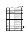
PU disconnection
A communication error has occurred between
the PU and the inverter.
The communication interval has exceeded the
permissible time period during RS-485
communication via the PU connector.
The number of communication errors has
exceeded the number of retries.
Connect the parameter unit cable securely.
Check the communication data and communication settings.
Increase the Pr. 122 PU communication check time interval
setting, or set "9999" (no communication check).
Retry count excess
Operation restart within the set number of retries
has
fai
led.
Eliminate the cause of the error preceding this error indication.
Function Name Description Corrective action Display