


1
1
Product checking and parts identification
1 OUTLINE
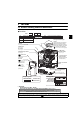
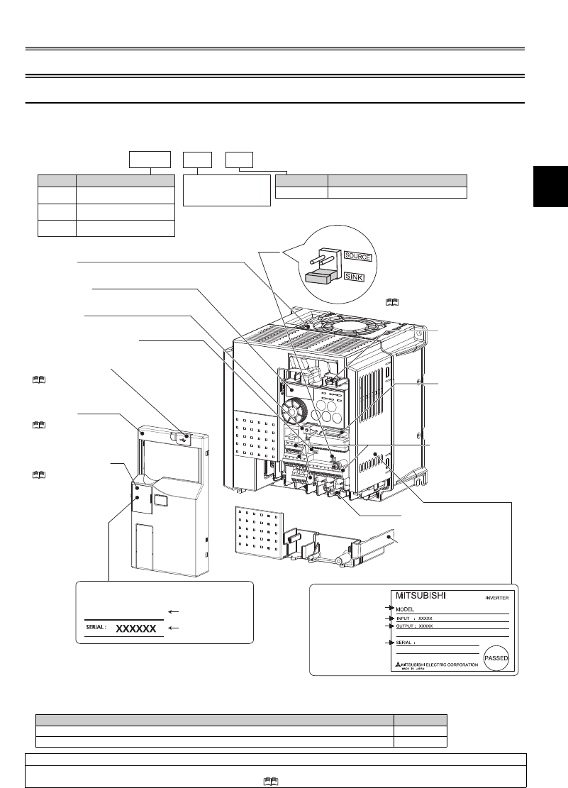
1.1 Product checking and parts identification
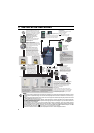
Unpack the inverter and check the capacity plate on the front cover and the rating plate on the inverter side face to ensure that
the product agrees with your order and the inverter is intact.
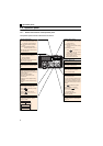
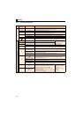
Inverter model
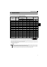
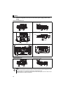
Accessory
· Fan cover fixing screws (M3
35mm)
These screws are necessary for compliance with the EU Directive
(Refer to page 49)
Capacity Quantity
FR-E720-1.5KSC to 3.7KSC, FR-E740-1.5KSC to 3.7KSC, FR-E720S-0.75KSC to 2.2KSC 1
FR-E720-5.5KSC to 15KSC, FR-E740-5.5KSC to 15KSC 2
Harmonic suppression guideline (when inverters are used in Japan)
All models of general-purpose inverters used by specific consumers are covered by "Harmonic suppression guideline for consumers who
receive high voltage or special high voltage". (For further details, refer to Chapter 3 of the Instruction Manual (Applied).)
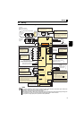
Connector for plug-in
option connection
(Refer to the instruction
manual of options.)
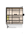
Inverter model
Serial number
Capacity plate
FR-E740-3.7KSC
Rating plate
Inverter model
Input rating
Output rating
Serial number
FR-E740-3.7KSC
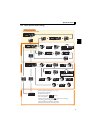
E740 3.7 KFR
--
Represents the
inverter capacity [kW]
E720
Three-phase 200V class
E740
Three-phase 400V class
E720S
Single-phase 200V class
No. Voltage class
Control circuit terminal specificationSymbol
Safety stop function modelSC
SC
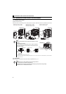
Cooling fan
The cooling fan is removable.
USB connector
(mini-B connector)
(Refer to page 9)
Control logic switchover jumper
connector
The jumper connector is in the sink logic
(SINK) when shipped from the factory.
Move the jumper connector to change to
the source logic (SOURCE). Always fit the
jumper connector to the either position.
( Refer to the Instruction Manual (Applied))
Combed shaped wiring cover
Refer to the Instruction Manual
(Applied) for installation/removal.
Main circuit terminal block
(Refer to page 10)
PU connector cover
Refer to the
Instruction Manual
(Applied) for how to
open the cover.
Front cover
Refer to the Instruction
Manual (Applied) for
installation/removal.
USB connector cover
Refer to the Instruction
Manual (Applied) for how to
open the cover.
Voltage/current input switch
(Refer to page 9)
Operation panel
(Refer to page 2)
PU connector
(Refer to page 9)
Example of FR-E740-3.7KSC
Control circuit terminal
block
(Refer to page 10)