


Installation MultiAccess Quick Start Guide
4 Multi-Tech Systems, Inc. PN 82001423L
Installation
Site Planning
With proper planning, your MultiAccess system can be installed quickly and in a short time. To implement the
suggested planning process, you must:
1. Plan for physical space, environmental, electronic and electrical needs. Identify physical installation site. The
environment should be properly ventilated with controlled temperature and humidity.
• Good AC power source with proper Earth Ground.
• EIA 19” rack, MultiComTower, or standalone installation.
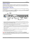
• Determine where the termination point is for each T1, PRI, or E1 line.
• Determine physical access point to the Ethernet network.
• Identify high quality category 5 cable for Ethernet & T1 cabling. Depending on environment characteristics,
shielded T1 cable may be necessary.
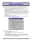
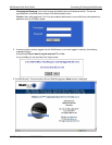
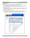
• For initial setup and administrative purposes, a network workstation with a WEB browser supporting HTTPS will
be needed.
2. Define your users’ client computer needs
• Determine the number of dial in analog modem users
• Identify client workstation OS (PC running Windows®98/XP/2000, or MAC OS10)
• Identify client modem types (V.34, V.90, V.92)
• Identify dial up security protocol (CHAP & PAP)
• Third-Party Security Devices (SecurID)
• Identify the Security Database (i.e. user file in RADIUS server or Microsoft SAM\Active directory with IAS) and
make sure users have dial in rights with framed protocol PPP attribute
3. Identify applicable network resources (IP address of; gateway/default route, DNS, WINS, RADIUS server(s), etc)
• Identify the network MASK
• Identify available IP addresses (determine the static IP address that is to be assigned to the Multi Access)
• Determine IP assignment method (predefined pool/range) to be implemented by the MultiAccess (regarding the
IP addresses to be assigned to the remote dial in users).
• When Implementing RADIUS Authentication and Accounting, identify the UDP ports used by the RADIUS
server(s)
4. Define your line interfaces
• Obtain T1 or E1 PRI line provisioning information for your LEC
• Identify the telephone number(s) of the line or lines
• Identify the Framing Format
• Identify the Line Coding
• Identify the type of signaling (RBS or PRI for T1 or E1 PRI)
• For RBS, the signaling type can be referred to as the start method and/or the FXS signaling method (i.e.
Immediate, Wink, Ground, and Loop)
• For PRI signaling identify the type of central office switch\protocol, i.e. AT&T5ESS, DMS100/250, National
ISDN2
• Identify the Line Build-Out (LBO) i.e. what db level is presented on premise by the provider and what db level
should the premise equipment transmit at.
Note: For E1 lines the signaling type must be PRI. R2 signaling methods are not supported.