


HPLA/HPHA-SERIES 46" WALK-BEHIND TROWEL — OPERATION AND PARTS MANUAL — REV. #6 (07/06/10) — PAGE 17
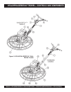
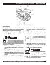
(Figures 3) shows the location of the basic controls or
components, for the HPLA/HPHA-SERIES 46" trowel. Listed
below is a brief explanation of each control or component
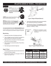
1. Quick Pitch™ Control Handle – To adjust the pitch of
the blades, grasp the handle then squeeze and either move
the handle forward or backward to achieve the desired
blade pitch.
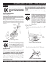
2. Handlebar Adjuster – Change the angle/height of the
handle bars by loosening star wheel, adjust handlebars to
desired location, tighten starwheel firmly to hold handlebars
in that position.
3. Hand Grip/Handle Bar – When operating the trowel, place
both hands on each grip to maneuver the trowel. Replace
hand grips when they become worn or damaged.
4. Throttle Control Lever – Controls the speed of the engine.
Pull the hand grip toward the operator to increase engine
speed (high), away from the operator to decrease engine
speed (low or idle).
5. Throttle (Engine) – Controls engine speed when throttle
control lever is pulled toward the operator.
6. V-Belt Cover – Remove this cover to gain access to the V-
belt. NEVER operate the trowel with this cover removed.
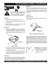
7. Centrifugal Safety Stop Switch – In the event the operator
loses control of the trowel, this switch will shut-down the
engine.
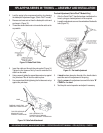
8. Auxiliary Lifting Tube - Use this tube to lift the trowel onto
a slab. Tube is to be inserted into socket located in front of
the gearbox.
9. Stabilizer Ring – Reduces trowel arm vibration. Helps
stabilize trowel arm.
10. Trowel Lifting Point – Insert the auxiliary lifting tube here.
See Figure 20.
11. Pitch Control (standard models) - Turn this "Star Wheel"
clockwise for increase blade pitch, and counter-clockwise
for decrease blade pitch.
12. Blades – This trowel is equipped with combination blades.
These blades are versatile and should take care of most
troweling needs. In addition float discs can be attached to
the trowel arms that will allow the trowel to float on "wet"
concrete.
13. Main Tube - When disassembling components inside the
tube exercise extreme CAUTION! Tube is spring-loaded,
severe injury could result if not disassembled correctly.
14. Guard Ring- NEVER! put hands or feet inside guard ring.
15. Engine – This trowel uses an 11HP Honda gasoline
engine.
16. Trowel Arm – NEVER operate the trowel with a bent, broken
or out of adjustment trowel arm. If the blades show uneven
wear patterns or some blades wear out faster than others,
the trowel arm may need to be adjusted. Use the trowel
arm adjustment tool P/N 1817 to adjust the trowel arms.
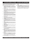
HPLA/HPHA-SERIES 46" TROWEL— CONTROLS AND COMPONENTS