


HPLA/HPHA-SERIES 46" WALK-BEHIND TROWEL — OPERATION AND PARTS MANUAL — REV. #6 (07/06/10) — PAGE 33
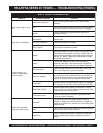
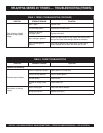
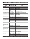
HPLA/HPHA-SERIES 46" TROWEL — MAINTENANCE (TROWEL)
■
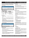
Does the trowel have a perceived rolling or bouncing
motion when in use?
■
Look at the trowel while it is running, does the guard
ring “rock up and down” relative to the ground?
2. Start engine, and bring trowel blades up to full speed and look
for the following conditions:
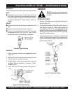
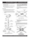
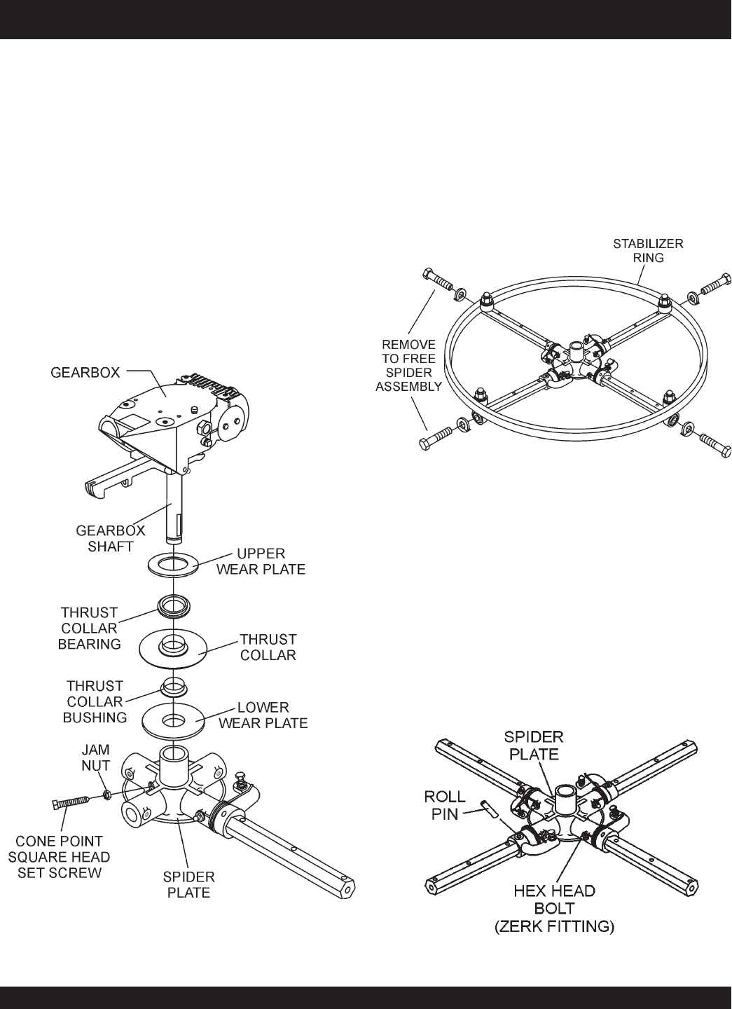
a. Locate the cone point square head set screw (Figure 43)
and attached jam nut found on the side of the spider
assembly.
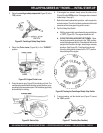
Spider Removal
1. Once it is determined that an adjustment is required, remove
the spider assembly from the gearbox shaft as follows:
Figure 43. Spider/Gearbox Removal
b. Loosen the jam nut and cone point square head set
screw, and carefully lift the
upper trowel assembly
off
of the spider assembly. A slight tap with a rubber mallet
may be necessary to dislodge the spider from the main
shaft of the gearbox.
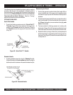
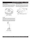
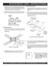
c. If the trowel is equipped with an outer stabilizer ring
(Figure 44), remove the four bolts at the end of each
spider arm.
Figure 44. Stabilizer Ring
d. Examine stabilizer ring for out of round or bends. If ring
is damaged, replace ring. If ring is found to be correct with
no damage, set aside.
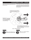
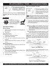
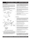
Trowel Arm Removal
1. Each trowel arm is held in place at the spider plate by a hex
head bolt (zerk grease fitting) and a roll pin. Remove both the
hex head bolt and the roll pin (Figure 45) from the spider
plate.
2. Remove the trowel arm from the spider plate.
Figure 45. Removing Roll Pin
and Zerk Grease Fitting