


HPLA/HPHA-SERIES 46" WALK-BEHIND TROWEL — OPERATION AND PARTS MANUAL — REV. #6 (07/06/10) — PAGE 19
HPLA/HPHA-SERIES 46" TROWEL — ASSEMBLY AND INSTALLATION
Assembly and Installation
Before the trowel can be put into operation there are some
components that must be installed before the trowel can be used.
This section provided general instructions on how to install those
components. Instruction sheet P/N 20485 provides further details
for the handle assembly.
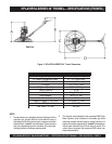
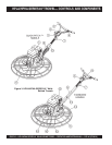
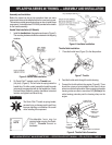
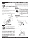
Handle Tube Installation (All Models)
1. Install the
handle tube
to the gearbox as shown in (Figure 5).
The mounting hardware should be contained in the shipping
container.
Figure 5. Handle Tube Installation
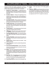
CAUTIONCAUTION
CAUTIONCAUTION
CAUTION
The Quick-Pitch™ handle is spring loaded,
personal injury or damage could result from
improper handling or installation. Be careful
when installing this component.
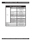
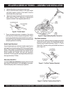
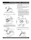
2. On Quick-Pitch™ models, pivot the
T-handle
back
(full pitch) (Figure 6). This will relax the spring inside the
handle tube. On either model, spread the handle bar ends
just enough to engage the teeth on the handle tube. Attach
the hand wheel assembly, position handlebar to desired
location, and tighten hand wheel firmly.
Figure 6. Handlebar Installation
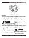
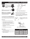
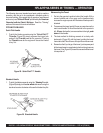
2. Feed the throttle cable through the cable housing.
3. Connect the throttle cable to the engine. (Figure 8). There
should be a piece of wire installed on the trowel to show
where to route the throttle cable. When connecting the cable
housing, make sure that no more than
1/4" (6.4mm)
of the
cable housing protrudes past the housing clamp on the
engine.
Figure 8. Throttle Cable Connection
CABLE HOUSING
ENGINE
THROTTLE
LEVER
SWIVEL STOP
SCREW
THROTTLE
CABLE END
CABLE
HOUSING
CLAMP
Figure 7. Throttle
Throttle Cable Installation
1. Place the throttle lever (Figure 7) to the idle position.
Considerable force may be
required when moving the Quick-
Pitch™ T-handle forward or
backward.
NOTE