


HPLA/HPHA-SERIES 46" WALK-BEHIND TROWEL — OPERATION AND PARTS MANUAL — REV. #6 (07/06/10) — PAGE 35
Trowel Arm Adjustment
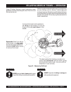
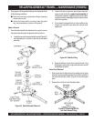
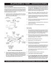
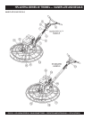
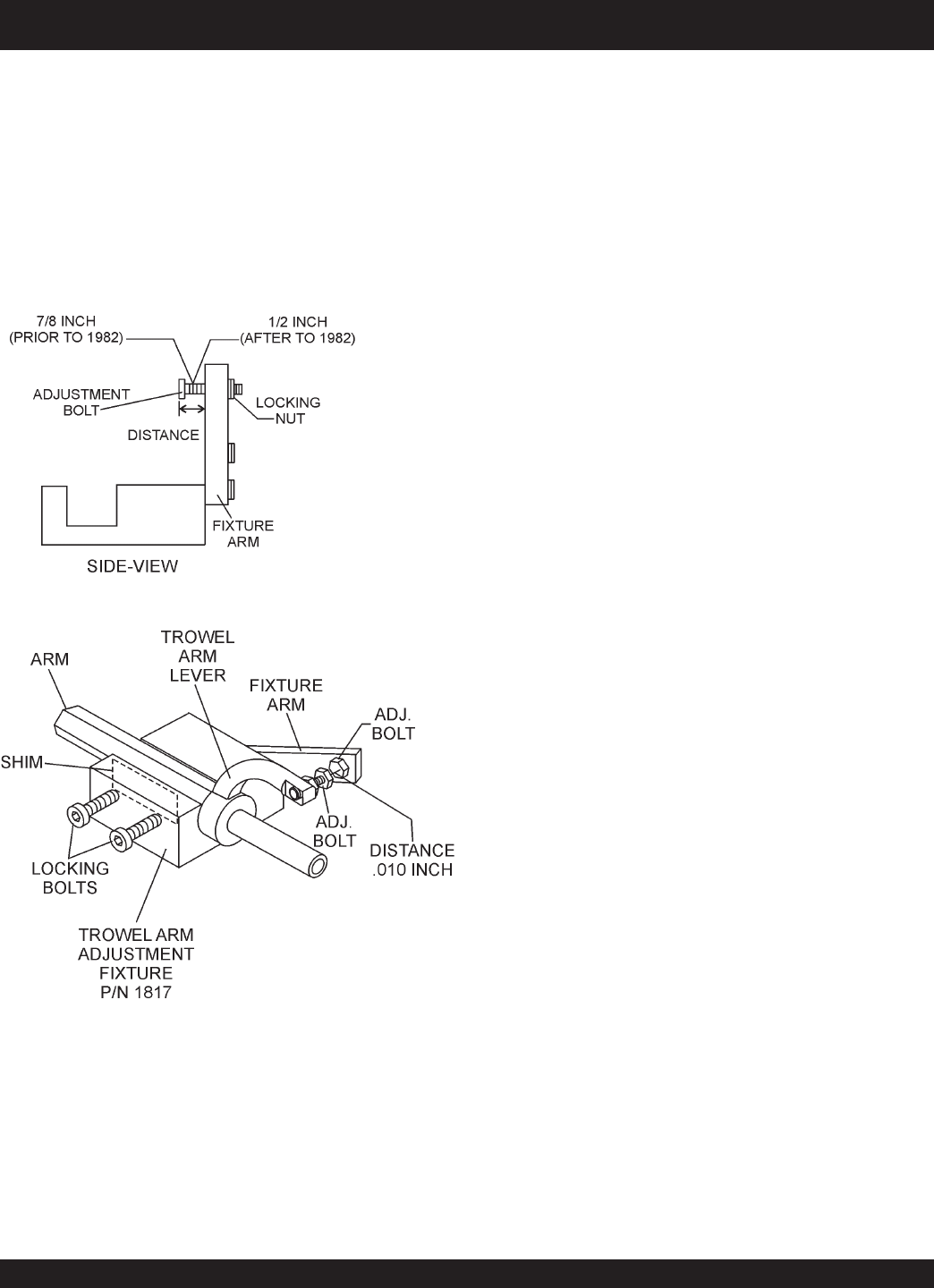
Shown in (Figure 49) is the adjustment fixture with a trowel arm
inserted. As each trowel arm is locked into the fixture, the arm bolt
is adjusted to where it contacts a stop on the fixture. This will
consistently adjust all of the trowel arms, keeping the finisher as
flat and evenly pitched as possible.
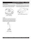
1. Locate the trowel arm adjustment tool P/N 1817. Set the
adjustment tool for a clock-wise blade rotation, meaning the
fixture arm is in the "UP" position.
Figure 49. Trowel Arm Adjustment Tool
HPLA/HPHA-SERIES 46" TROWEL — MAINTENANCE (TROWEL)
2. Trowels manufactured prior to June of 1982 require that the
distance from the end of the adjusting bolt and the fixture arm
must be 7/8" (Figure 49). Conversely, trowels manufactured
after June of 1982 require that the distance from the end of
the adjusting bolt and the fixture arm must be 1/2".
3. Un-screw the locking bolts on the adjustment tool, and place
the trowel arm into the adjustment fixture channel as shown
in (Figure 49). A
thin shim
may be required to cover the
blade holes on the trowel arm. Make sure to align the trowel
adjustment bolt with the fixture adjustment bolt.
4. Using an allen wrench, tighten the locking bolts on the
adjustment tool and securely lock the trowel arm in place.
5. Loosen the locking nut on the trowel arm lever, then turn the
trowel arm adjusting bolt until it barely touches (.010") the
adjusting bolt on the fixture.
6. After the correct adjustment has been made, tighten lock nut
on trowel arm lever to lock in place.
7. Loosen locking bolts on adjustment fixture, and remove
trowel arm from fixture.
8. Repeat steps 2-7 for the remaining trowel arms.
Re-Assembly
1. Clean and examine the upper/lower wear plates and thrust
collar. Examine the entire spider assembly. Wire brush any
concrete or rust build-up. If any of the spider components are
found to be damaged or out of round, replace them.
2. Make sure that the bronze trowel arm bushing is not damage
or out of round. Clean the bushing if necessary. If the bronze
bushing is damage or worn, replace it.
3. Reinstall bronze bushing onto trowel arm.
4. Repeat steps 2 -3 for each trowel arm.
5. Make sure that the spring tensioner is in the correct position
to exert tension on the trowel arm.
6. Insert all trowel arms with levers into spider plate (with bronze
bushing already installed) using care to align grease hole on
bronze bushing with grease hole fitting on spider plate.
7. Lock trowel arms in place by tightening the hex head zerk
grease fitting and jam nut.
8. Re-install the blades back onto the trowel arms.
9. Install stabilizer ring onto spider assembly.
10. Reinstall lower wear plate,
thrust collar
and
upper wear
ring
in the
reverse order
that they were dis-assembled onto
the spider shaft. Make sure that there is little or no lateral
movement between the thrust collar and the spider shaft.