21
P/N: 307271
4.9 COMPRESSOR OIL THERMOSTATIC VALVE
The oil thermostatic valve acts as a thermostatically controlled by-pass valve and allows varying amounts
of oil, depending upon the temperature, to by-pass cooler during the warm up period. When circulated oil
reaches a temperature of 140 º F, the valve closes the by-pass completely and all the oil is circulated though
the cooler. The oil cooler by-pass is restricted enough to cause some warm oil to flow through the cooler
during the warm-up period, maintaining a higher average compressor oil temperature. This reduces
condensation in the oil system and also reduces the possibility of a slug of cold oil from the cooler, causing
a momentary high restriction and a temporary reduction in the oil pressure, hence oil flow.
CLEANING OIL THERMOSTAT
1. If it becomes necessary to take the thermostat apart and clean it, disassemble at the bolted flange
and remove the element.
2. If coated or dirty, clean as necessary. The element and rubber seal ring should be cleaned only with
hot water.
3. Inspect the element for bent or dented parts.
4. Replace any damage part during cleaning and assembling the pipe openings should be closed with
tape or plugs until pipe connections made.
4.10 COMPRESSOR AIR/OIL SEPARATOR
WARNING
The separator element is located in the top of the air-oil receiver/separator tank. Here the oil mist contained
in the air is removed prior to the final discharge of air. Air should be taken only from the outlet service
valves on the center of the top end of the separator-never directly from the receiver/separator fittings on the
side of the tank. When the oil vapor in the discharge air becomes excessive, the separator element may
need replacing. This should not be necessary more than once a year under normal operating conditions.
SEPARATOR ELEMENT REPLACEMENT
1. The element may be replaced by removing the head from the top of separator and pulling the
element out. Only a factory element should be used as a replacement.
2. The separator element flange must have a gasket on each side to seal the head on one side and the
vessel on the other. The staple in each gasket must be left in the gasket, it acts as a static ground.
3. Re-torque the head bolts uniformly to a specification of 220ft-1b.(dry) or 170ft-lb. (wet) when
replacing the separator head.
4.11 BELTS & BELT ADJUSTMENT
Visually inspect the belts. Replace belts if cracked or frayed. Check engine manual for proper belt tension.
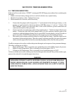
DO NOT REMOVE CAPS, PLUGS OR OTHER COMPONENTS WHEN COMPRESSOR
IS RUNNING OR PRESSURIZED. PERSONAL INJURY WILL RESULT. BEFORE
DOING SO, STOP COMPRESSOR AND RELIEVE ALL INTERNAL PRESSURE.


