


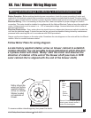
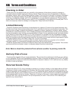


XII. Fan / Blower Wiring Diagram
Wiring should always be done by a licensed electrician!
10 HP Pulley Drive Owners Manual
O.A.S. 2007
c
Before Operation - Before making electrical power connections, check for proper grounding of motor and
application. All electrical contacts and connections must be properly insulated and enclosed. Coupling, belts,
chains or other mounted devices must be in proper alignment, balance and secure to insure safe motor operation.
Electrical Wiring - Prior to connecting to the power line, check motorplate for proper voltage and rotation
connection. This motor should be installed in compliance with the National Electrical Code and any other applicable
codes. Voltage at motor not to exceed + or - 10% of nameplate voltage. Licensed electrician should make all
electrical connections.
Always use the wire diagram on the motor plate. Sometimes the wire diagrams on the motor will be for different
rotation. Wire for counter-clockwise rotation.
12
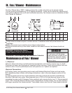
Ground: Connect house ground
wire to green chassis screw in
motor wire housing box.
Motor
Wire
Box
Green
Chassis
Screw
***
To reverse rotation interchange any two power line leads.
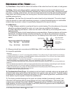
Electrical Disconnects - Every motor driven fan should have an independent disconnect switch to isolate the
unit from the electrical supply. It should be near the fan and must be capable of being locked by maintenance
personnel while servicing the unit, in accordance with OSHA procedures.
Locate factory applied rotation arrow on blower cabinet to establish
rotation direction. It is not possible to know beforehand, which direction
a 3-phase motor will rotate. Bump start the motor and observe the
direction of rotation of the end of the blower shaft (see hole in NYB
outer cabinet that is aligned with the end of the blower shaft.)
Motor should be
wired per factory
applied rotation
arrow on cabinet.
Sticker located
on backside of
blower.
Follow Motor Plate for wiring diagram.