


-
6
-
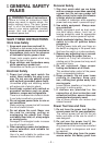
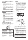
7) Do not strain the tool by holding the speed
control trigger halfway (speed control
mode) so that the motor stops.
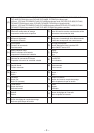
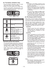
Symbol Meaning
V
Volts
Direct current
n
0
No load speed
… min
-1
Revolutions or reciprocations
per minutes
Ah
Electrical capacity of battery
pack
IV
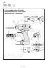
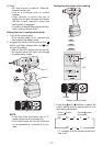
. ASSEMBLY
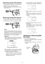
Attaching or Removing Bit
NOTE:
•
When attaching or removing a bit, discon-
nect battery pack from tool or place the
switch in the center position (switch lock).
1. Hold the collar of quick connect chuck and
pull it out from the tool.
2
. Insert the bit into the chuck. Release the
collar.
3.
The collar will return to its original position
when it is released.
4.
Pull the bit to make sure it does not come out.
5. To remove the bit, pull out the collar in the
same way.
CAUTION:
•
If the collar does not return to its origi-
nal position or the bit comes out when
pulled on, the bit has not been properly
attached. Make sure the bit is properly
attached before use.
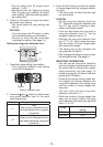
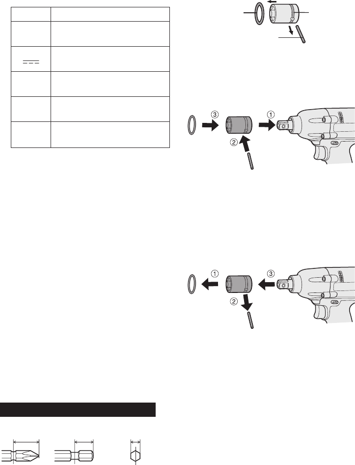
EYFLA4A/EYFLA4AR/EYFLA5A/EYFLA5AR
12 mm
(15/32")
9 mm – 9.5 mm
(
23/64" – 3/8")
6.35 mm
(1/4")
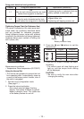
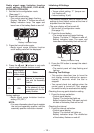
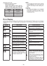
Attaching Socket (Pin type)
• Remove the socket’s rubber ring and pin.
rubber
ring
pin
groove
1 Attach the socket to the tool.
2 Insert
the pin. (Taking care to align the pin
holes on the socket and tool.)
3 A
ttach the rubber ring by sliding it into place
over the groove.
NOTE:
Be sure to attach the rubber ring to prevent
the pin from falling out.
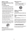
Removing Socket (Pin type)
1 Remove the rubber ring.
2 Remove the pin.
3 R
emove the socket from the tool.
NOTE:
Keep the temperature of the tool above
the
freezing point (0°C/32°F) when attach-
ing sockets to or detaching them from
the square drive on the tool. Do not use
excessive
force when attaching or detach-
ing sockets.