


20
Xxxxx Xxxxxxxx
Xxxxx Xxxxxxxx
Xxxxx Xxxxxxxx
20
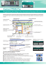
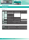
Note 1: Current inputs can be converted into voltage inputs by attaching the supplied external resistor to the input terminal section.
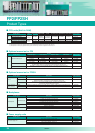
Item
Rated load voltage
Max. load current
Max. surge current
OFF state leakage current
ON state maximum
voltage drop
Repose time
Power supply
for driving
internal circuit
Input points per common
Connection method
Voltage
Current
OFF
→
ON
ON
→
OFF
FP2-Y6R
5A 250VAC (10A/common)
5A 30VDC (10A/common)
Min. load: 100mA
10V (resistor load)
−
−
−
−
−
−
10ms or less
8ms or less
24VDC±10%
(21.6V to 26.4VDC)
70mA or less
2 points/common
Terminal block
(M3 screw)
FP2-Y16R
2A 250VAC (5A/common)
2A 30VDC (5A/common)
Min. load: 100µA
10V (resistor load)
−
−
−
−
−
−
10ms or less
8ms or less
24VDC±10%
(21.6V to 26.4VDC)
160mA or less
8 points/common
Terminal block
(M3 screw)
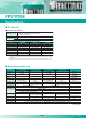
NPN open
collector
16-point type
FP2-Y16T
−
5-24VDC
0.5A (at 12 to 24VDC)
0.1A (at 5VDC)
3A 10ms or less
1µA or less
0.5V or less
0.1ms or less
0.3ms or less
4.75 to 26.4VDC
120mA
or less
(at 24VDC)
8 points/common
Terminal block
(M3 screw)
PNP open
collector
16-point type
FP2-Y16P
−
5-24VDC
0.5A (at 12 to 24VDC)
0.1A (at 5VDC)
3A 10ms or less
1µA or less
0.5V or less
0.1ms or less
0.3ms or less
4.75 to 26.4VDC
70mA
or less
(at 24VDC)
8 points/common
Terminal block
(M3 screw)
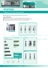
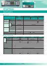
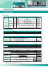
Relay output unit Transistor output unit
I/O mixed unit (output side)
NPN
open collector
FP2-Y32T
5-24VDC
0.1A (at 12 to 24VDC)
50mA (at 5VDC)
0.3A
1µA or less
1V or less
(at 6 to 26.4VDC)
0.5V or less
(at 6VDC or less)
0.1ms or less
0.3ms or less
4.75 to 26.4VDC
140mA
or less
(at 24VDC)
32 points/common
One 40-pin
connector
NPN
open collector
FP2-Y64T
5-24VDC
0.1A (at 12 to 24VDC)
50mA (at 5VDC)
0.3A
1µA or less
1V or less
(at 6 to 26.4VDC)
0.5V or less
(at 6VDC or less)
0.1ms or less
0.3ms or less
4.75 to 26.4VDC
250mA
or less
(at 24VDC)
32 points/common
Two 40-pin
connectors
PNP
open collector
FP2-Y32P
5-24VDC
0.1A (at 12 to 24VDC)
50mA (at 5VDC)
0.3A
1µA or less
1.5V or less
(at 6 to 26.4VDC)
0.5V or less
(at 6VDC or less)
0.1ms or less
0.3ms or less
4.75 to 26.4VDC
150mA
or less
(at 24VDC)
32 points/common
One 40-pin
connector
PNP
open collector
FP2-Y64P
5-24VDC
0.1A (at 12 to 24VDC)
50mA (at 5VDC)
0.3A
1µA or less
1.5V or less
(at 6 to 26.4VDC)
0.5V or less
(at 6VDC or less)
0.1ms or less
0.3ms or less
4.75 to 26.4VDC
270mA
or less
(at 24VDC)
32 points/common
Two 40-pin
connectors
FP2
-
XY64D2T
5-24VDC
0.1A (at 12 to 24VDC)
50mA (at 5VDC)
0.3A
1
µ
A or less
1V or less
(at 6 to 26.4VDC)
0.5V or less
(at 6VDC or less)
0.1ms or less
0.3ms or less
4.75 to 26.4VDC
120mA
or less
(at 24 VDC)
32 points/common
Two 40-pin
connectors
FP2
-
XY64D2P
5-24VDC
0.1A (at 12 to 24VDC)
50mA (at 5VDC)
0.3A
1
µ
A or less
1.5V or less
(at 6 to 26.4VDC)
0.5V or less
(at 6VDC or less)
0.1ms or less
0.3ms or less
4.75 to 26.4VDC
130mA
or less
(at 24 VDC)
32 points/common
Two 40-pin
connectors
Rated control capacity
6-point type 16-point type
Voltage
Current
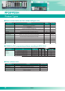
Item
Item
Number of output points
Output range
(digital input)
Resolution
Conversion speed
Overall accuracy
Insulation method
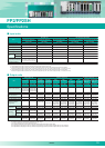
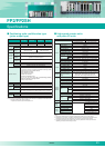
Analog output
Analog output unit FP2-DA4
4 channels
±10V (K-2048 to K+2047)
0 to 20mA (K0 to K4095)
1/4096
500µs/ch
±1.0% F.S. or less (0 to 55°C)
– Between the output terminal and FP2 internal circuits: Photocoupler – Between channels: No insulation
Hold/Non-hold setting by shared memory setting
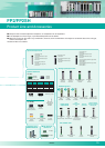
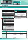
1. Analog input
2. Analog output
− − − − − −
note 1)
note 2) note 2)
note 3) and 4)
Number of input points
Voltage
Current
Thermocouple
R.T.D
Voltage
Current
Thermocouple
R.T.D
Input range
(resolution)
Conversion
speed
Overall accuracy
Insulation method
Digital output
Broken wire sensing
Input range change method
Averaging
Offset setting
FP2-AD8X FP2-RTD FP2-AD8VI
±10V
1V
±
5V
±100mV
(1/65536)
(1/13107)
(1/65536)
S: 0 to +1500
°C
J: -200 to +750°C
J: -100 to +400°C
K: -200 to +1200°C
K: -200 to +1000°C
K: -200 to +600°C
T: -200 to +350°C
R: 0 to +1500°C
N: -200 to +1300°C
(0.1
°C)
(0.1°C)
(0.1°C)
(0.1°C)
(0.1°C)
(0.1°C)
(0.1°C)
(0.1°C)
(0.1°C)
Pt 100 : -200 to +650°C
Pt 100 : -100 to +200°C
JPt 100 : -200 to +650°C
JPt 100 : -100 to +200°C
JPt1000 : -100 to +100
°C
(0.1°C)
(0.1°C)
(0.1°C)
(0.1°C)
(0.1
°C)
500µs/ch (insulated), 5ms (insulated)
−
20ms/ch
20ms/ch
Voltage: ±0.1% FS (25 °C) Voltage temperature coefficient: ±0.3% (0 to 55 °C)
Between the input terminal and FP2 internal circuits: Photocoupler and DC/DC converter
Between the input terminal and FP2 internal circuits: Photocoupler
Between channels: PhotoMOS relay
Selectable from 3 to 64 times for each channel (Moving average after cutting the maximum and minimum values)
Selectable from K -2048 to +2047 for each channel
Each channel (only when a thermocouple or RTD is inputted)
Each channel
Batch switching of all channels: By the range setting switch
Each channels: By shared memory setting
−
−
−
−
note1)
−
−
−
−
−
− −
−
20ms/ch
±0.3% F.S. (0 to 55°C)
500µs/ch
500µs/ch
±1.0% F.S. (0 to 55°C)
−
−
−
(1/65536)
(1/13107)
(1/32768)
(1/13107)
±
10V
1V to 5V
±20mA
4mA to 20mA
8 channels8 channels 8 channels
DC input type/
Transistor output
(NPN) type
DC input type/
Transistor output
(PNP) type
Notes: The number of ON points that can be actuated simultaneously is limited by the input voltage and the ambient temperature.
The maximum load current is limited by the external power supply voltage.
1) The current capacity of each common terminal is 5A max.
2) The maximum load current of the transistor output unit is limited by the external power supply voltage.
3) The specifications also apply to the DC-input, transistor-output (NPN) type I/O-mixed unit with ON pulse catch input "FP2-XY64D7T".
4) The specifications also apply to the DC-input, transistor-output (PNP) type I/O-mixed unit with ON pulse catch input "FP2-XY64D7P".
Analog I/O units
FP2/FP2SH
Specifications
08/2007