


Xxxxx Xxxxxxxx
Xxxxx Xxxxxxxx
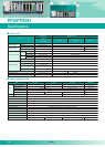
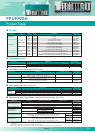
Item
Transistor Line driver
Output type
Number of axes controlled
Position
command
Speed
command
Acceleration/
deceleration
command
Home return
Operation mode
Startup time
Output interface
Feedback
counter
Other functions
Internal current consumption (at 5 VDC)
External power
supply
Command units
Max. pulse count
Command
range
Acceleration/
deceleration
“S” Acceleration/
deceleration
Acceleration/
deceleration time
Home return speed
Input terminals
Output terminals
Output mode
Countable range
Input mode
Voltage
Current consumption
FP2-PP21 FP2-PP41 FP2-PP22 FP2-PP42
21.6VDC to 26.4VDC
200mA max.
50mA
350mA max.
90mA
200mA max.
50mA
350mA max.
90mA
Notes: Previous FP2 positioning units FP2-PP2 and FP2-PP4 are not compatible with the multi-function
type FP2 positioning unit. Please contact us.
* 2-phase input cannot be used with multiples of one.
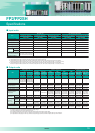
2-axis type
FP2-PN2AN
4-axis type
FP2-PN4AN
8-axis type
FP2-PN8AN
Speed control function
Torque control function
Product number
Home
return
Others
Communication speed
Cables
Connection system
Communication cycle/
Number of connectable stations
Transmission distance
Counter
Interrupt
−
Part no.
Product number
Output
specifi-
cations
Counter
Pulse
output
PWM
output
Insulation method
Rated voltage
Rated current
Input impedance
Usage voltage range
Min. ON voltage/Min. ON current
Min. OFFvoltage/Min. OFFcurrent
Response
time
Input time constant setting
Common method
Number of counter channels
Calculation range
Max. calculation speed
Input modes
Max. calculation speed
Other
Number of interrupt points
Interrupt processing
delays
Insulation method
Rated load voltage
Rated load voltage range
Max. load current
Leakage current when off
Max. voltage drop when on
Response
time
Surge absorber
Common method
External power
supply
Surge absorber
Channels
Max. output frequency
Output modes
Number of output points
Max. load current
Cycle
Duty
Item
Item
OFF
→
ON
ON
→
OFF
OFF
→
ON
ON
→
OFF
Voltage
Current
(when using 24VDC)
FP2 High-speed counter unit
FP2-HSCT (NPN)
FP2-HSCP (PNP)
FP2 Pulse I/O unit
FP2-PXYT (NPN)
FP2-PXYP (PNP)
Photocoupler insulation
24VDC
Approx. 7.5mA (when using 24VDC)
Approx. 3.2kΩ
20.4VDC to 26.4VDC
19.2V /6mA
5.0V /1.5mA
1µs or less
2µs or less
None, 4µs, 8µs, 16µs, 32µs (set in 2-input units)
16 points/common (+ common)
4 channels
32-bit with sign (–2147483648 to +2147483647)
200kHz
3 modes (direction control, individual input, phase input)
2.5µs
8 comparison outputs, multiplier function (1, 2, 4)
None, 1/unit, 8/unit (set with mode setting switches)
160µs max. (when using FP2 CPU unit)
50µs max. (when using FP2SH CPU unit)
Photocoupler insulation
5 to 24VDC
4.75VDC to 26.4VDC
0.1A (A11 to A18, B11 to B14 pins), 0.8A (B15 to B18 pins)
1µA max.
0.5V max.
1µs max.
1µs or less (NPN)
5µs or less (PNP)
Zener diode
16 points/common
20.4VDC to 26.4VDC
90mA or less (NPN)
200mA or less (PNP)
8 points (A11 to A18 pins)
4CH (B11 to B18 pins)
100kHz
2 modes (direction control, individual output)
4CH (B15 to B18 pins)
0.8A
1Hz to 30kHz
0 to 100% (unit: 1%)
1)
1)
2)
3)
3)
1)
1pps to 500kpps
(can set in 1pps)
1pps to 4Mpps
(can set in 1pps)
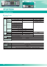
Unit specifications
Position
control
function
Control method
Interpolation control
Unit of control
Positioning data
Backup
Acceleration/
deceleration method
Acceleration/
deceleration time
Positioning range
Search method
Creep rate
Communication specifications
PTP control, continuous path (CP) control
Two/Three-axis linear interpolation, two-axis circular interpolation, three-axis helical interpolation
Pulse/µm/inch/degree
600 points per axis
Parameters and data tables can be saved in FROM
Linear/S-curve acceleration and deceleration
0 to 10,000ms (in increments of 1ms)
(-1073741823 to +1073741823 pulses) Increment/Absolute specification
Supported by a JOG operation (free-run operation)
Supported by a real-time torque control function
Home proximity (DOG) search
Can be set freely
Pulser input operation supported
Auxiliary output code and auxiliary output contact
Dwell time
In-position contact
100Mbps
Commercially available LAN straight cable (Category 5e shielded cable)
Ring
0.5ms, 8 axes max./system (Command cycle: 1ms)
Between terminals: 60m Total: 200m
2 axes, independent 4 axes, independent 2 axes, independent 4 axes, independent
Pulse unit (the program specifies whether Increment or Absolute is used.)
Signed 32 bits (–2147483648 to +2147483647 pulses)
Linear acceleration/deceleration,
S acceleration/deceleration (this takes the form of an “S”)
Can select from Sin curve, Secondary curve,
Cycloid curve and Third curve
0 to 32,767ms (can set in 1ms)
Speed setting possible (changes return speed and search speed)
Home input, Near home input, Over limit input (+), Over limit input (–)
Deviation counter clear output signal
E point control (Linear and S accelerations/decelerations selecting possible)
P point control (Linear and S accelerations/decelerations selecting possible)
Home return function (Home search)
JOG operation function
JOG positioning function
Pulser input function
Transfer multiplication ratio
(×1, ×2, ×5, ×10, ×50, ×100, ×500, ×1000 selecting possible)
Real-time frequency change function
Infinity output function
0.02ms or 0.005ms possible
1 pulse output (Pulse/Sign), 2 pulse output (CW/CCW)
Signed 32-bit (–2147483648 to +2147483647 pulse)
2-phase input*, Direction distinction input, Individual input (transfer multiple available for each)
The flag to compare the elapsed value is built-in
(The timing signal outputs at the optional position during an operation)
Notes:
1) This value is effective when the input time constant (filter) setting was set to "No setting".
2) If interrupts are used at the 1/unit setting, the interrupt from the external input terminal B1 (X8) or
the interrupt program from the comparison 0 (one of among INT16 to INT23) is booted.
3) At maximum load current and resistance load. There may be distortion in the output waveform,
depending on the load current and type of load.
23
Specifications
FP2/FP2SH
High-speed counter units
and pulse I/O units
S-LINK units
Performance Specification
Transmission specifications for communication interface
16
−
−
−
−
−
−
Start-stop synchronization
−
−
−
−
RS232C RS485
Note 1: The protocol can be downloaded from: www.panasonic-electric-works.com
Specifications
Item
Item 100BASE-TX
Item
FP2-MW
W mode
Token bus
Base band
500kbit/s
500kbit/s
500kbit/s, 250kbit/s
W2 mode
1)
F mode
Polling
Item
VE mode (PLC link) FL-net mode
Mode
Communication method
Transmission method
Transmission speed
Transmission
distance
Number of
connectable stations
Transmission error check
Synchronization
Interface
Transmission line
RAS function
Extendable to 800m
250kbits/s: 1200m max.
500kbits/s: 800m max.
Extendable to 800m
32 stations max.
Twisted-pair cable
Hardware self-diagnosis function
Twisted-pair cables
or VCTF cables
Extendable to 700m
CRC (cyclic redundancy check) system
Start-stop synchronization
RS485 compatible
S-LINK units
FP2-SL2
1
128 points max.
CPU unit with S-LINK ports
FP2-C1SL
2
128 points max. × 2
Item
Number of channels
Number of I/O
points
Rated power
supply voltage
Power
consumption
Transmission method
Synchronization
Transmission protocol
Transmission speed
Transmission distance
FAN-OUT
Connection method
* For FP2SH (Cannot be used for FP2)
1)
note 2) note 2)
note 3)
1)
1)
1)
2)
2)
10BASE5 : 500m
(
2500m)
10BASE-T : 100m
(
500m)
FL-net [FA link protocol (UDP/IP)]
MEWTOCOL
Communication
interface
Communication speed
Cycle time
example
Cable length
Communication protocol
Link
communication
specifications
Message communication
specifications
Number of nodes
Other functions
Ethernet
10BASE5/10BASE-T
10Mbit/s
50ms/32 units
(2048 points/2048 words)
Link relay
8192 points/unit
Link register
8192 words/unit
2048 bytes max.
(Compatible with MEWTOCOL)
99 units max.
Data transfer
Remote programming
Multilevel link communications
1024 bytes max.
(Not compatible with MEWTOCOL)
254 units max.
Interconnection with other
companies' units
Communication
block used
Interface
Communication
method
Synchronization
Transmission line
Transmission distance
Transmission speed
(To be set in the system register)
Transmission code
Transmission format
(To be set in the system register)
Number of stations
PLC link capacity
COM1
(upper channel)
COM2
(lower channel)
Number of attachable units
Supported versions
General-purpose serial communications
Computer link
(Panasonic open protocol "MEWTOCOL" should be used.)
1:1 communications 1:N communications 1:1 communications 1:N communications
FP2-CB232
FP2-CB422
RS232C RS422
Full duplex
FP2-CB232
FP2-CB422
RS232C RS422
Full duplex
FP2-CB232
FP2-CB422
Three-core or
five-core shielded wire
15m Length: 1200m max.
300 to 230,400bps
Twisted-pair cable
or VCTF
Length: 1200m max.
300 to 230,400bps
(19,200 bps when our C-NET adapter is connected)
99 stations max.
(32 stations max. when our C-NET adapter is connected)
−
99 stations max.
(32 stations max. when our C-NET adapter is connected)
−
16 stations max.
Link relay: 1024 points
Link register: 128 words
−
−
Three-core or
five-core shielded wire
15m Length: 1200m max.
300 to 230,400bps
Twisted-pair cable
or VCTF
Length: 1200m max.
300 to 230,400bps
(19,200 bps when our C-NET adapter is connected)
FP2-CB485
RS485
Two-wire half duplex
FP2-CB485
RS485
Two-wire half duplex
ASCII, JIS7, JIS8, and binary
Start code: With STX / Without STX
End code: CR/CR+LF/Time setting/ETX
Data length: 7 bits/8 bits
Parity: 0/Invalid/Valid (Odd/Even)
Stop bit: 1 bit/2 bits
23 units max. (including 8 units for the computer link and 2 channels for the PLC link)
CPU unit (both FP2 and FP2SH): Ver. 1.4 or later, FPWIN GR: Ver. 2.4 or later, FPWIN PRO: Ver. 5.1 or later
ASCII, JIS7, JIS8
PLC link function
Twisted-pair cable
or VCTF
1200m (RS485) 15m (RS232C)
115,200bps
Token passing
(Floating master)
1 master +
32 slave stations max.
Note 1: When the unit is used in W2 mode, it must be set by user programs.
The number of input and output points for each channel can be selected by the switch in the unit body
Input: 0/32/64/96/128 points Output: 0/32/64/96/128 points
+24VDC ±10% Maximum allowable ripples (P-P): ±10%
(S-LINK terminal block IN-24VDC 1.6 A or less)
[Current consumption of the S-LINK controller (incl. D-G line current
consumption)] +24VDC 1.6A or less
[Maximum allowable current supply (Supply to the S-LINK and I/O
devices through the 24V - 0V line)] +24VDC 5A (Fuse: 5A or less)
Bi-directional time division multiplex transmission
Bit/Frame synchronization
S-LINK protocol
28.5kbit/s
Main signal line: Extendable to 200m (max. 400m when a booster is used)
320
T-branch multi-drop wiring or standard multi-drop wiring
[+24, 0V, D-G (with a function of D-G short-circuit protection)]
Notes: 1) Refer to the "Power Capacity Determination" section of SUNX Limited's S-LINK Design
Manual for details of the current consumption.
2) Refer to SUNX Limited's S-LINK Design Manual for the booster and FAN-OUT.
100Mbit/s
Base band
100m
205m (2 segments)
Category 5 UTP cable
−
−
−
100BASE-T
10Mbit/s
Base band
100m
500m (5 segments)
Category 3, 4 and 5 UTP cable
−
−
−
100BASE5
10Mbit/s
Base band
500m
2500m (5 segments)
Transceiver cable
50m
100 nodes/segment
Integer multiples of 2.5m
A
A
A
A
A
A
A
A
A
N/A
A: Available
N/A: Not available
* The lengths in parentheses are
available when a repeater is used.
Notes 1) Switching between 100BASE-TX and 10BASE-T is done automatically by auto negotiation function.
2) The standards cite 100m as the maximum, but noise resistance measures such as attaching a ferrite
core may be necessary in some cases, depending on the usage environment. Also, if the hub is
positioned close to a control board, we recommend using it at a distance of 10m or less.
3) The standards cite 50m as the maximum, but noise resistance measures such as attaching a ferrite
core may be necessary in some cases, depending on the usage environment. Also, if the transceiver is
positioned close to a control board, we recommend using it at a distance of 5m or less.
Communications function
Number of communication connections
Transparent
communications buffer
Transmit
Receive
- MEWTOCOL-COM: computer link function (max. 2KB)
- MEWTOCOL-DAT: data transfer (max. 1020 words)
- Transparent communication
8 connections max.
Factory setting: 1k words/connection x 3
Factory setting: 1k words/connection x 3
Transmission speed
Transmission method
Max. segment length
Max. distance between nodes
Communication cable or connection
Max. transceiver cable
length
Max. number of nodes
Node spacing
Item
Transistor Line driver
Output type
Number of axes controlled
Position
command
Speed
command
Acceleration/
deceleration
command
Home return
Operation mode
Startup time
Output interface
Feedback
counter
Other functions
Internal current consumption (at 5 VDC)
External power
supply
Command units
Max. pulse count
Command
range
Acceleration/
deceleration
“S” Acceleration/
deceleration
Acceleration/
deceleration time
Home return speed
Input terminals
Output terminals
Output mode
Countable range
Input mode
Voltage
Current consumption
FP2-PP21 FP2-PP41 FP2-PP22 FP2-PP42
21.6VDC to 26.4VDC
200mA max.
50mA
350mA max.
90mA
200mA max.
50mA
350mA max.
90mA
Notes: Previous FP2 positioning units FP2-PP2 and FP2-PP4 are not compatible with the multi-function
type FP2 positioning unit. Please contact us.
* 2-phase input cannot be used with multiples of one.
2-axis type
FP2-PN2AN
4-axis type
FP2-PN4AN
8-axis type
FP2-PN8AN
Speed control function
Torque control function
Product number
Home
return
Others
Communication speed
Cables
Connection system
Communication cycle/
Number of connectable stations
Transmission distance
Counter
Interrupt
−
Part no.
Product number
Output
specifi-
cations
Counter
Pulse
output
PWM
output
Insulation method
Rated voltage
Rated current
Input impedance
Usage voltage range
Min. ON voltage/Min. ON current
Min. OFFvoltage/Min. OFFcurrent
Response
time
Input time constant setting
Common method
Number of counter channels
Calculation range
Max. calculation speed
Input modes
Max. calculation speed
Other
Number of interrupt points
Interrupt processing
delays
Insulation method
Rated load voltage
Rated load voltage range
Max. load current
Leakage current when off
Max. voltage drop when on
Response
time
Surge absorber
Common method
External power
supply
Surge absorber
Channels
Max. output frequency
Output modes
Number of output points
Max. load current
Cycle
Duty
Item
Item
OFF
→
ON
ON
→
OFF
OFF
→
ON
ON
→
OFF
Voltage
Current
(when using 24VDC)
FP2 High-speed counter unit
FP2-HSCT (NPN)
FP2-HSCP (PNP)
FP2 Pulse I/O unit
FP2-PXYT (NPN)
FP2-PXYP (PNP)
Photocoupler insulation
24VDC
Approx. 7.5mA (when using 24VDC)
Approx. 3.2kΩ
20.4VDC to 26.4VDC
19.2V /6mA
5.0V /1.5mA
1µs or less
2µs or less
None, 4µs, 8µs, 16µs, 32µs (set in 2-input units)
16 points/common (+ common)
4 channels
32-bit with sign (–2147483648 to +2147483647)
200kHz
3 modes (direction control, individual input, phase input)
2.5µs
8 comparison outputs, multiplier function (1, 2, 4)
None, 1/unit, 8/unit (set with mode setting switches)
160µs max. (when using FP2 CPU unit)
50µs max. (when using FP2SH CPU unit)
Photocoupler insulation
5 to 24VDC
4.75VDC to 26.4VDC
0.1A (A11 to A18, B11 to B14 pins), 0.8A (B15 to B18 pins)
1µA max.
0.5V max.
1µs max.
1µs or less (NPN)
5µs or less (PNP)
Zener diode
16 points/common
20.4VDC to 26.4VDC
90mA or less (NPN)
200mA or less (PNP)
8 points (A11 to A18 pins)
4CH (B11 to B18 pins)
100kHz
2 modes (direction control, individual output)
4CH (B15 to B18 pins)
0.8A
1Hz to 30kHz
0 to 100% (unit: 1%)
1)
1)
2)
3)
3)
1)
1pps to 500kpps
(can set in 1pps)
1pps to 4Mpps
(can set in 1pps)
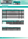
Unit specifications
Position
control
function
Control method
Interpolation control
Unit of control
Positioning data
Backup
Acceleration/
deceleration method
Acceleration/
deceleration time
Positioning range
Search method
Creep rate
Communication specifications
PTP control, continuous path (CP) control
Two/Three-axis linear interpolation, two-axis circular interpolation, three-axis helical interpolation
Pulse/µm/inch/degree
600 points per axis
Parameters and data tables can be saved in FROM
Linear/S-curve acceleration and deceleration
0 to 10,000ms (in increments of 1ms)
(-1073741823 to +1073741823 pulses) Increment/Absolute specification
Supported by a JOG operation (free-run operation)
Supported by a real-time torque control function
Home proximity (DOG) search
Can be set freely
Pulser input operation supported
Auxiliary output code and auxiliary output contact
Dwell time
In-position contact
100Mbps
Commercially available LAN straight cable (Category 5e shielded cable)
Ring
0.5ms, 8 axes max./system (Command cycle: 1ms)
Between terminals: 60m Total: 200m
2 axes, independent 4 axes, independent 2 axes, independent 4 axes, independent
Pulse unit (the program specifies whether Increment or Absolute is used.)
Signed 32 bits (–2147483648 to +2147483647 pulses)
Linear acceleration/deceleration,
S acceleration/deceleration (this takes the form of an “S”)
Can select from Sin curve, Secondary curve,
Cycloid curve and Third curve
0 to 32,767ms (can set in 1ms)
Speed setting possible (changes return speed and search speed)
Home input, Near home input, Over limit input (+), Over limit input (–)
Deviation counter clear output signal
E point control (Linear and S accelerations/decelerations selecting possible)
P point control (Linear and S accelerations/decelerations selecting possible)
Home return function (Home search)
JOG operation function
JOG positioning function
Pulser input function
Transfer multiplication ratio
(×1, ×2, ×5, ×10, ×50, ×100, ×500, ×1000 selecting possible)
Real-time frequency change function
Infinity output function
0.02ms or 0.005ms possible
1 pulse output (Pulse/Sign), 2 pulse output (CW/CCW)
Signed 32-bit (–2147483648 to +2147483647 pulse)
2-phase input*, Direction distinction input, Individual input (transfer multiple available for each)
The flag to compare the elapsed value is built-in
(The timing signal outputs at the optional position during an operation)
Notes:
1) This value is effective when the input time constant (filter) setting was set to "No setting".
2) If interrupts are used at the 1/unit setting, the interrupt from the external input terminal B1 (X8) or
the interrupt program from the comparison 0 (one of among INT16 to INT23) is booted.
3) At maximum load current and resistance load. There may be distortion in the output waveform,
depending on the load current and type of load.
Positioning units: multifunction type
(pulse output type)
FP2/FP2SH
Specifications
08/2007