


Installing the gateway router 31
SmartNode 4520 & 4110 Series User Manual 3 • Hardware installation
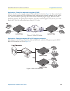
Location and mounting requirements
The SmartNode router is intended to be placed on a desktop or similar stur
dy, flat surface that offers easy
access to the cables. Allow sufficient space at the rear of the chassis for cable connections. Additionally, you
should consider the need to access the unit for future upgrades and maintenance.
Installing the gateway router
SmartNode gateway router installation consists of the following:
• Placing the devic
e at the desired installation location (see section “Mounting the gateway router” on
page 31)
• Installing the
interface and power cables (see section “Connecting cables” on page 31)
When you finish installing the SmartNode, go to chapter 4, “G
etting started with the SmartNode” on page 38.
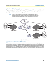
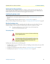
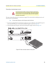
Mounting the gateway router
Place the router on a desktop or similar sturdy, flat sur
face that offers easy access to the cables. The router
should be installed in a dry environment with sufficient space to allow air circulation for cooling.
Note For proper ventilation, leave at least 2 inches (5 cm) to the left, right, front,
and rear of the SmartNode gateway router.
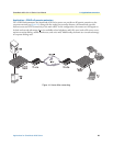
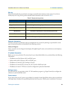
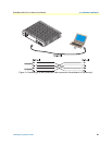
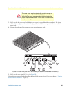
Connecting cables
WARNING
Do not work on the system or connect or disconnect cables during
periods of lightning activity.
CAUTION
The Interconnecting cables shall be acceptable for external use
and shall be rated for the proper application with respect to volt-
age, current, anticipated temper
ature, flammability, and
mechanical serviceability.
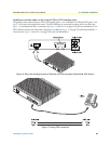
Installing router cables takes place in the following order:
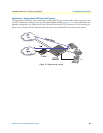
1. I
nstalling the RJ-11 voice port (FXS) cable or cables (see “Installing an interface cable on the router’s FXS
and FXO interface ports”)
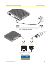
2. I
nstalling the 10/100 Ethernet port cable or cables (see “Installing the Ethernet cable” on page 34)
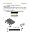
3. I
nstalling the power input (see “Connecting to external power source” on page 36)