


6
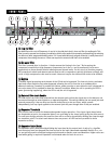
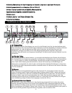
((77)) CCoommpprreessssoorr TThhrreesshhoolldd
This sets the point that compression action begins. Any signal above this threshold will be compressed at
the amount set by the ratio control. If it drops below this point‚ the compressor has no affect. At the
maximum setting‚ the compressor will be out of circuit for all signals except very high peaks. At the
minimum setting‚ the source will be continuously compressed.
((88)) CCoommpprreessssoorr RRaattiioo
This varies the amount of compression. It is the ratio of the input level to the output level. A ratio of 4:1
signifies that the input level has increased four times as fast as the output (the dynamic range is
compressed by a factor of 4). If the ratio is 1:1 the output exactly tracks the input and there is no
compression. Ratios of 2:1 to 4:1 are typically used for vocals and musical instruments. High ratios
provide a soft limiting function‚ since the compressor uses a soft-knee design. To disable compression‚
set the ratio to 1:1.
((99)) CCoommpprreessssoorr AAttttaacckk
Sets the speed at which the compressor circuit responds to an increase in the input level. Minimum
settings allow it to act quickly so that fast transients do not get through. High settings slow down the
response time to let the signal settle before acting upon it. (Useful for those situations when you want
percussive attacks but still need compression.)
((1100)) CCoommpprreessssoorr RReelleeaassee
Sets the time which the compressor circuit takes to track the input after a drop in level. Low settings will
cause the compressor to follow the signal closely so that rapid input changes will not be lost during
compression. Higher settings smooth out compression effects.
((1111)) LLiimmiitteerr TThhrreesshhoolldd
The limiter is an infinite ratio compressor. The threshold control defines the point that absolute limiting
begins. The limit LED will light when this threshold has been exceeded. To disable limiting‚ set this
control to maximum.
((1122)) GGaaiinn
Adjusts the post-processing gain to make up for compression loss. It does not adjust the input level. The
input levels should be set by the source equipment to 0 dBu or +4 dBu for best noise performance. The
input and output levels are monitored by an LED meter so that gain can be applied to the signal. A twelve-
segment LED array tells how much gain reduction is being applied to the signal. If this meter is not active
there is no change to the input signal. It is very useful for making adjustments‚ since the action of all
controls is easily seen.
((1133)) IInnppuutt//OOuuttppuutt LLeevveell MMeetteerr SSwwiittcchh
This is a peak indicating meter that is connected to either the output or the input. When in the out
position‚ the LEDs display the output and when depressed‚ the LEDs display the input.
((1144)) SStteerreeoo LLiinnkk
If the compressor is to be used with stereo signals‚ the link switch should be pressed. This gives true
RMS summing for an accurate representation of the levels of Channel A and B and locks them together to
maintain the stereo image during processing. When the link switch is pressed‚ Channel A’s controls
become the masters and affect both channels. The controls for Channel B are disabled. The meters of
Channel B will still reflect the VCA and input/output levels‚ just as in the dual-mono mode.
((1155)) PPoowweerr SSwwiittcchh
Power is applied to the unit when this switch is pressed.