


10
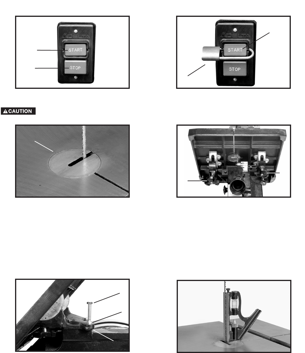
Fig. 19
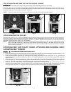
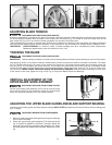
TABLE INSERT
Place the table insert (A) Fig. 19 in the hole provided in the table. Engage the protrusion on the insert in the indent (B) in the table.
TILTING THE TABLE
1. The table on the machine can be tilted 45 degrees to the right and 10 degrees to the left. To tilt the table to the right, loosen
the two locking knobs (A) Fig. 20, tilt the table to the desired angle, then re-tighten two locking knobs (A).
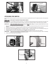
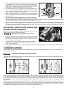
2. To tilt the table to the left, loosen the two locking knobs (A) Fig. 20, and tilt the table to the right until the table stop (A) Fig. 21
is accessible. Remove the table stop (A) Fig. 21, and tilt the table to the left. Tighten the two locking knobs (A) Fig. 20.
ADJUSTING THE TABLE STOP
The machine is equipped with an adjustable table stop (A) Fig. 21 that allows the table to be set at 90 degrees to the blade.
Tilt the table to the right until the table stop (A) Fig. 21 contacts the table. Place a square on the table against the blade (Fig. 22).
Check to see if the blade is 90 degrees to the table surface. If not, do the following:
1. Tilt the table slightly to the left and tighten the table lock knobs.
2. Loosen the locknut (B) Fig. 21 to free the adjustment nut (A) Fig. 21. Turn the adjustment nut (A) right or left to raise or lower
the table stop.
3. Lower the table. Check to see that the table is 90 degrees to the blade (Fig. 22). If it is, raise the table, hold the stop (A) Fig. 21
and tighten nut (B).
Fig. 20
Fig. 21
Fig. 22
B
A
A
A
B
C
Fig. 17
Fig. 18
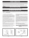
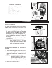
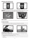
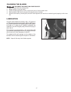
To start the machine, press the “START” button (K) Fig. 17. To stop the tool, press the “STOP” button (L) Fig. 17.
When the machine is not in use, the switch should be locked in the “OFF” position to prevent
unauthorized use, using a padlock (M) Fig. 18 with a 3/16" diameter shackle
K
L
K
M
STARTING AND STOPPING SAW