


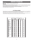

11
ADJUSTING BLADE TENSION
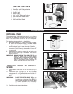
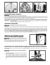
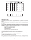
A series of graduations is located on the back of the upper wheel slide bracket. These graduations indicate the proper tension
for various widths of blades. With the blade on the wheels, turn the knob (A) Fig. 23 to raise or lower the wheel, until the red
fiber washer (D) Fig. 25 is in line with the proper graduation for the size of the blade used.
These graduations are correct for average work, and will not be affected by rebrazing of the saw blade. Use these graduations
until you become familiar enough with the operation of the band saw to vary the tension for different kinds of blades or work.
OVER-STRAINING is a common cause of blade breakage and other unsatisfactory blade performance.
Release the blade tension when the machine is not in use.
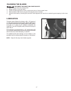
TRACKING THE BLADE
Before tracking the blade, be certain that the blade guides and blade support bearings do not touch the blade.
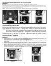
After applying tension to the blade, rotate the wheels slowly forward by hand and observe the blade’s movement. The blade
(A) Fig. 24 should travel just to the front of the center of the upper tire. If the blade creeps toward the front edge, loosen the
wing nut (B) Fig. 25, and tighten the thumb screw (C). This will draw the blade toward the center of the tire. If the blade creeps
toward the back edge, turn the thumb screw in the opposite direction. Adjust the thumb screw (C) Fig. 25 only a fraction of a
turn each time. NEVER TRACK THE BLADE WHILE THE MACHINE IS RUNNING. After the blade is tracking just to the front
of the center of both tires, tighten the wing nut (B) Fig. 25. Adjust the Blade Guides and Bearings.
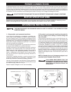
VERTICAL ADJUSTMENT OF THE
UPPER BLADE GUIDE ASSEMBLY
DISCONNECT MACHINE FROM POWER SOURCE.
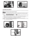
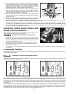
Set the upper blade guide assembly (A) Fig. 26 as close as possi-
ble to the top surface of the workpiece. Loosen the lock knob (B)
and move the guide assembly (A) to the desired position.
Fig. 23 Fig. 24 Fig. 25
Fig. 26
A
A
B
C
A
B
D
IMPORTANT:
IMPORTANT:
DISCONNECT MACHINE FROM POWER SOURCE.
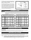
ADJUSTING THE UPPER BLADE GUIDES AND BLADE SUPPORT BEARING
Adjust the upper blade guides and blade support bearings ONLY AFTER the blade has the correct tension and is tracking prop-
erly. To adjust:
DISCONNECT MACHINE FROM POWER SOURCE.
1. Make sure that the bottom blade guides and support bearings
do not touch the blade.
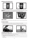
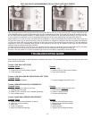
2. Check the upper blade guide assembly. The blade guides (A)
Fig. 27 should be parallel to the blade. To adjust, loosen the
screw (B) and rotate the complete guide assembly (C). When
the blade guides are parallel with the blade, tighten the screw
(B).
Fig. 27
A
C
B
DISCONNECT MACHINE FROM POWER SOURCE.