


7
ASSEMBLY
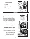
OPTIONAL STAND
The optional stand is shipped top-down in the shipping
container with the motor mounted to the inside top of the
stand. The on/off switch is wired to the end of the power
cord.
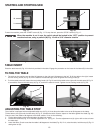
To make the motor operational, do the following:
1. Remove the stand (A) Fig. 4 from the shipping container.
Be careful not to crimp the switch cord that extends
through the top of the stand. NOTE: Set the stand on
several blocks of wood to raise the stand off the floor.
2. Take the panel (B) Fig. 4 off of the stand (A) by removing
two screws (C) and loosening the two other screws (D).
Remove the panel on the opposite side of the stand in
the same way.
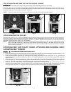
3. Remove the two mounting screws that are holding the
motor (F) Fig. 5 to the top of the stand. One screw is
shown at (E) Fig. 5.
DO NOT REMOVE THE CABLE TIE (G) that
holds the switch cord (H) to the vertical
mounting bar (J) unless the accessory height
attachment will be used on the tool. This
cable tie will prevent contact between the
switch cord and the motor pulley or belt.
Fig. 4
Fig. 5
Fig. 6
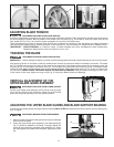
ATTACHING MOTOR TO OPTIONAL
STAND
1. Turn the stand on its side with the two bars (B) Fig. 6
down.
2. Position the motor (C) Fig. 6 on the two horizontal
support bars (B), and fasten with the four 5/16-18 x 2"
carriage bolts and flanged nuts, two of which are shown
at (D).
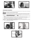
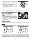
PLACE THE MOTOR SHAFT (E) on the
same side of the stand as the large open-
ing in the top of the stand (See (B) Fig. 7)
before loosely tightening the carriage bolts
(D). Further alignment will be necessary
after the saw is attached to the stand.
3. Carefully turn the stand right side up.
A
B
C
D
F
H
G
J
E
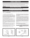
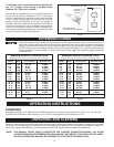
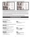
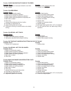
1. Band Saw with Pulleys attached
2. Large V-Belt
3. Small V-Belt
4. Motor Pulley
5. 3/4" to 5/8" Reducing Bushing
6. Belt and Pulley Guard Clamp
7. Key
8. Belt and Pulley Guard
CARTON CONTENTS
1
2
3
4
5
7
6
8
IMPORTANT:
IMPORTANT: