


12
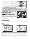
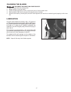
Fig. 30
Fig. 31
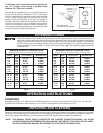
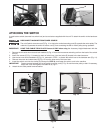
When using the machine for wood cutting (3000 SFM), pull the shifter knob (A) Fig. 30 all the way out so that the lugs of the
clutch (B) are engaged with the hub (C) of the drive pulley. This action will disengage the clutch (D) from the hub (E) of the gear
that transmits power through the gear box. It may be necessary to rotate the pulley manually in order to line up the clutch lugs
with the slots in the hub of the pulley. This action provides a direct drive from the motor pulley to the drive pulley, by-passing
the gear box.
When using the machine for metal cutting (40, 60, 85, 115, 160, 220, and 335 SFM), push the shifter knob (A) Fig. 31 all the way
in, disengaging the clutch (B) from the hub (C) of the pulley. An additional clutch (D) is located inside the band saw. It must be
engaged with the hub (E) of the gear that transmits power through the gear box. When pushing in on the shifter knob (A) Fig.
31, rotate the lower wheel of the band saw to feel when the engagement occurs.
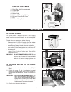
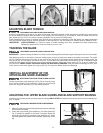
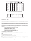
3. Adjust the guides (A) Fig. 28, so that the front edge of the guides
are just behind the “gullets” of the saw teeth. The complete guide
block bracket can be moved in or out by loosening the thumb
screw (C) Fig. 28 and turning the knurled knob (D) Fig. 28. When
the guides (A) are set properly, tighten thumb screw (C).
4. Two set screws (B) Fig. 28 hold the upper blade guides (A) in
place. Loosen the set screws (B) to move the guides (A). Place
them as close as possible to the side of the blade. (Be careful not
to pinch the blade). Tighten the screws (B).
5. When the blade guide wears to a point that it cannot be adjusted
close to the blade, loosen screw (B) Fig. 28 and reverse the blade
guides (A) Fig. 28.
6. The upper blade support bearing (E) Fig. 28 prevents damage to
the set in the saw teeth by keeping the blade from being pushed
too far toward the back. The support bearing (E) should be set 1/64" behind the blade by loosening the thumb screw (F)
and turning the knurled knob (G) to move the support bearing (E) in or out.
7. Adjust the blade support bearing (E) so that the back edge of the blade overlaps the outside diameter of the ball bearing
by about 1/16". The bearing (E) is set on an eccentric. To change the position, remove the screw (H) and bearing (E) Fig.
28. Loosen the thumb screw (F), back out the knurled knob from the set screw. Remove the hex shaft from the hole, and
rotate it to move the eccentric for the bearing.
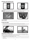
ADJUSTING LOWER BLADE GUIDES AND
BLADE SUPPORT BEARING
Adjust the lower blade guides and blade support bearing after the the
upper guides and bearing have been adjusted.
1. Adjust the front edge of the guide blocks (B) so that they are just
behind the “gullets” of the saw teeth. Turn the knurled knob (C) Fig.
29 to make this adjustment. Check the support bearing. It should not
be touching the back of the blade.
2. Loosen the two screws (A) Fig. 29. Move the guides (B) as close
as possible to the side of the blade, being careful not to pinch the
blade. Tighten screws (A).
3. Turn the other knurled knob (E) to adjust the lower blade support bearing (D) Fig. 29 so that it is about 1/64" behind the back
of the blade.
Fig. 28
Fig. 29
A
D
G
E
H
F
C
A
C
E
A
B
A
B
D
B
B
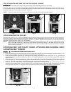
CHANGING SPEEDS
An advantage of this machine is that it can be changed instantly from a slow-speed metal cutting band saw to a standard high-
speed wood cutting band.
DISCONNECT MACHINE FROM POWER SOURCE.
Be certain that the band saw is in the “off” position and the power is disconnected when changing from either metal-to-wood
cutting or from wood-to-metal cutting.
DISCONNECT MACHINE FROM POWER SOURCE.