


8
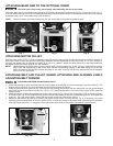
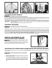
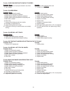
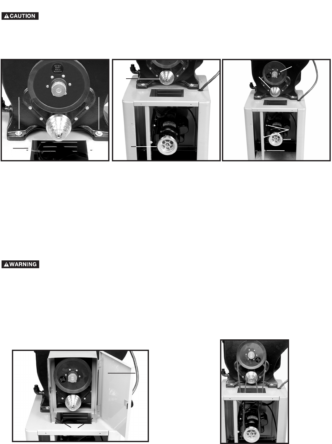
ATTACHING BELT AND PULLEY GUARD, ATTACHING AND ALIGNING V-BELT,
ADJUSTING BELT TENSION
DISCONNECT MACHINE FROM POWER SOURCE.
1. Use a straight edge to align the inside grooves of the pulleys (A) and (B) Fig. 9 to the inside edge of the drive pulley (C). The
pulleys can be moved in or out on the shafts and the motor can also be moved.
2. Place the belt and pulley guard (A) Fig. 10A over the belt opening and position the two clamps (B) over the guard flanges
and under the top of the stand. Use the four 1/4-20 x 1/2” round head screws in the holes in the bottom of the clamps to
fasten in place.
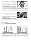
3. Attach the largest V-Belt to the inside groove of the motor pulley (A) Fig. 9 and to the drive pulley (C) Fig. 9. Attach the small-
er V-Belt to any one of the remaining three grooves of the motor pulley (A) and the corresponding groove of the gear box
pulley (A). (Fig. 10B shows belts in place. Belt and pulley guard was removed for clarity.)
4. Adjust the belt tension by raising or lowering the motor on the motor mounting bars (D) Fig. 9. If necessary, the motor
mounting can be repositioned on the two posts (E) Fig. 9. Keep the pulleys in alignment when performing this operation.
With light finger pressure, a 1" deflection in the belt at the center span of the pulleys indicates the proper tension.
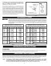
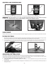
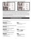
ATTACHING MOTOR PULLEY
Both the motor pulley (A) Fig. 8, and the gearbox pulley (B) are four-step pulleys and should always be attached inverted to
each other. Check to see if the gear box pulley (B) is attached with the largest step of the pulley in the “in” or “out” position. In
this case, the largest step of the gear box pulley (B) is in the “in” position. Attach the motor pulley (A) to the motor shaft with
the largest step of the motor pulley in the “out” position.
When attaching the motor pulley (A) to the motor shaft, use the supplied 3/4" to 5/8" reducing bushing on the motor
shaft. Place the supplied key in the motor shaft. Position the reducing bushing on the shaft, being sure to line the
split in the reducer with the key. Position the pulley on the shaft. Line it up with the key. Secure with the two supplied
5/16-18 x 5/16" set screws.
Fig. 8Fig. 7
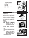
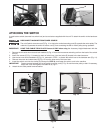
ATTACHING BAND SAW TO THE OPTIONAL STAND
The band saw is very heavy. Use a helper when attaching the saw to the stand.
Attach the band saw to the optional stand using the four holes provided (two are shown at (A) Fig. 7). Place one 5/16 -18 x 1-
3/4" hex head screw with one 5/16" flat washer through each hole through the bottom of the band saw and the top of the stand,
and attach with a 5/16" lock washer, and 5/16-18 hex nut.
Screws, washers, and nuts for attaching the saw to the stand come with the optional stand.
Fig. 9
Fig. 10A
E
D
C
A
B
B
A
A
A
A
B
Fig. 10B
NOTE:
NOTE:
B