


10
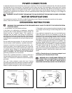
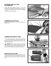
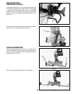
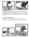
Fig. 17
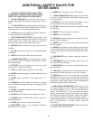
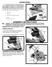
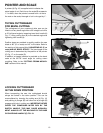
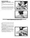
Fig. 16
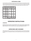
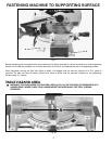
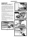
Fig. 18
POINTER AND SCALE
A pointer (A) Fig. 16, is supplied which indicates the
actual angle of cut. Each line on the scale (B) represents
1°. In effect, when the pointer is moved from one line to
the next on the scale, the angle of cut is changed by 1°.
TILTING CUTTINGHEAD
FOR BEVEL CUTTING
The cuttinghead of your compound miter saw can be
tilted to cut any bevel angle from a 90°
straight cut-off to
a 45
° left bevel angle by loosening bevel lock handle (A)
Fig. 17, tilting cutting arm (B) to the desired angle and
tightening lock handle (A).
Positive stops are provided to rapidly position the saw
blade at 90° (0° on scale) and 45° to the table. Refer to
the section of this manual titled “ADJUSTING 90° (0° on
scale)
AND 45
° BEVEL STOPS”. The bevel angle of the
cutting arm is determined by the position of the pointer
(C) Fig. 17, on the scale (D).
In addition, a triangle indicator is provided on the bevel
scale at the 33-7/8° bevel angle for cutting crown
moulding. Refer to the “CUTTING CROWN MOULD-
ING” section of this manual.
LOCKING CUTTINGHEAD
IN THE DOWN POSITION
When transporting the saw, the cuttinghead should
always be locked in the down position. This can be
accomplished by lowering the cutting arm (A) Fig. 18,
and pushing in plunger (B) until other end of plunger (B)
engages with hole in cutting arm. IMPORTANT: NEVER
CARRY THE COMPOUND MITER BOX BY THE
SWITCH HANDLE. THIS MAY CAUSE MISALIGN-
MENT. ALWAYS LIFT THE MACHINE BY THE BASE
OR CARRYING HANDLE (C) FIG. 18.
B
A
C
A
D
B
A
C
B