


1313131313
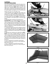
Fig. 28
Fig. 29
Fig. 30
Fig. 31
A
C
B
D
A
E
F
G
B
A
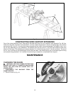
Fig. 32
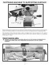
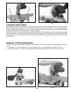
ADJUSTING DOWNWARD
TRAVEL OF SAW BLADE
1. DISCONNECT THE SAW FROM THE POWER
SOURCE.
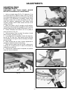
2. The downward travel of the saw blade can be limit-
ed to prevent the saw blade from contacting any metal
surfaces of the machine. This adjustment is made by
loosening locknut (A) Fig. 32, and turning adjusting
screw (B) in or out. Then tighten locknut (A).
3. When making this adjustment, MAKE SURE THE
MACHINE IS DISCONNECTED FROM THE POWER
SOURCE and lower the blade as far as possible as
shown in Fig. 32. Rotate the blade by hand to make cer-
tain the teeth do not contact any metal surfaces and
adjust if necessary.
ADJUSTING 90° AND 45°
BEVEL STOPS
1. DISCONNECT THE SAW FROM THE POWER
SOURCE.
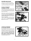
2. Loosen bevel lock handle (H) Fig. 29, and move the
cutting arm all the way to the right, then tighten the bevel
lock handle.
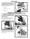
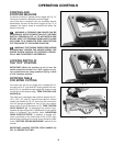
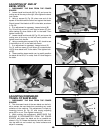
3. Using a square (A) Fig. 28, place one end of the
square on the table and the other end against the blade.
Check to see if the blade is at 90° to the table, as shown
in Fig. 28.
4. If an adjustment is necessary, loosen locknut (B)
Fig. 29, and turn screw (C) until head of screw (C) con-
tacts casting (D) when blade is 90° to the table. Then
tighten locknut (B).
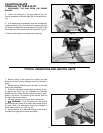
5. Loosen bevel lock handle (H) Fig. 29, and move the
cutting arm all the way to the left bevel position and
tighten bevel lock handle.
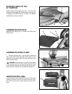
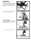
6. Using a combination square (A) Fig. 30, check to see
if the blade is at 45° to the table, as shown.
7. If an adjustment is necessary, loosen locknut (E)
Fig. 31, and turn screw (F) until screw (F) contacts cast-
ing (G) when blade is 45° to the table. Then tighten lock-
nut (E).
8. These positive stops enable you to rapidly position
the blade at the 90° (0° on scale) and 45° bevel angle to
the table.
H