7
Fig. 5
Fig. 7
Fig. 8
C
A
C
B
D
Fig. 6
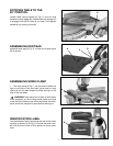
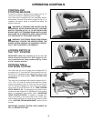
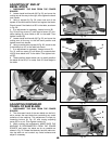
ROTATING TABLE TO THE
90° POSITION
Loosen table locking handle (A) Fig. 5, one turn and
squeeze locking trigger (B). Rotate table until plunger (C)
is engaged into the 90° stop (0° on scale). Then tighten
handle (A) by turning clockwise.
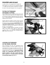
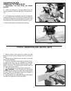
ASSEMBLING DUST BAG
Assemble dust bag (A) Fig. 6, to free end of dust spout
(B) as shown.
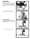
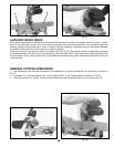
ASSEMBLING WORK CLAMP
1. The work clamp (A) Fig. 7, can be used on either the
right or left side of the saw base. Insert post of work
clamp (A) into the hole located on either the right or left
side of the saw base.
WARNING: Keep hands out of path of saw blade.
If the workpiece you are cutting would cause your hand
to be within the hazard zone of the saw blade, the work-
piece should be clamped in place before making cut.
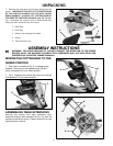
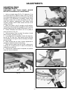
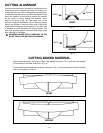
IDENTIFICATION LABEL
The identification label is located at the rear of the motor
housing as shown at (D) Fig. 8. Record the serial num-
ber onto the front cover of this manual for future refer-
ence.
A
A
B


