


1919191919
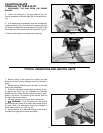
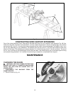
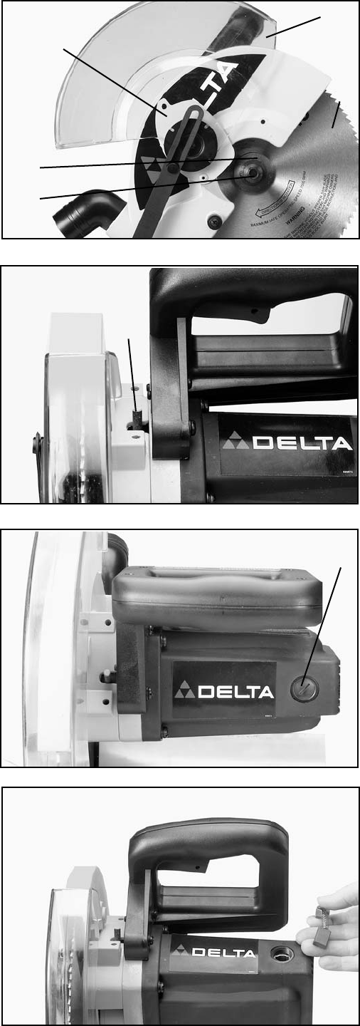
Fig. 50
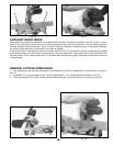
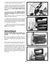
Fig. 51
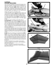
Fig. 52
D
C
E
F
Fig. 53
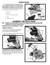
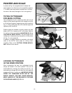
3. Rotate arbor cover (B) Fig. 50, and lower guard (G)
to the rear, exposing arbor screw (C), as shown.
4. Remove arbor screw (C) Fig. 50, by turning screw
clockwise with wrench supplied while at the same time
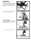
pressing in on arbor lock (D) Fig. 51, to keep the arbor
from turning. Remove outside blade flange (E) Fig. 50,
and saw blade (F). DO NOT REMOVE INSIDE BLADE
FLANGE.
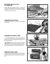
5. Assemble new saw blade MAKING CERTAIN
TEETH OF SAW BLADE ARE POINTING DOWN AT
THE FRONT, AS SHOWN and assemble outside blade
flange (E)
Fig. 50, making sure flats on outside blade flange are
engaged with flats on arbor shaft.
6. Thread arbor screw (C) Fig. 50, into saw arbor by
turning screw (C) counterclockwise as far as possible by
hand. Then tighten arbor screw (C) with wrench supplied
while at the same time pressing in on arbor lock (D) Fig.
51, to keep arbor from turning.
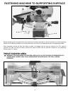
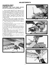
7. Rotate arbor cover (B) Fig. 50, and lower guard (G)
to the front and replace screw that was removed in
STEP 2 and securely tighten.
BRUSH INSPECTION
AND REPLACEMENT
CAUTION: BEFORE INSPECTING BRUSHES, DIS-
CONNECT THE MACHINE FROM THE POWER
SOURCE.
Brush life varies. It depends on the load on the motor.
Check the brushes after the first 50 hours of use for a
new machine or after a new set of brushes has been
installed.
After the first check, examine them after about 10 hours
of use until such time that replacement is necessary.
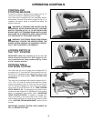
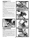
The brush holders (A) Fig. 52, are located on the motor
housing opposite each other. Fig. 53, illustrates one of
the brushes removed for inspection. When the carbon
on either brush is worn to 3/16" in length or if either
spring or shunt wire is burned or damaged in any way,
replace both brushes. If the brushes are found service-
able after removing, reinstall them in the same position
as removed.
A
B
G
E
C
F