


12
Fig. 24
Fig. 25
Fig. 27
Fig. 23
H
G
Fig. 26
ADJUSTMENTS
ADJUSTING TABLE
POSITIVE STOPS
DISCONNECT SAW FROM POWER SOURCE
BEFORE PERFORMING ANY ADJUSTMENTS.
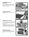
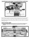
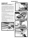
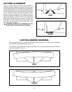
1. Using a straight edge (G) Fig. 23, determine if the
two fence halves are parallel to each other by placing
the straight edge against the front surfaces of the fence
as shown. If an adjustment is necessary, loosen fence
mounting screws, two of which are shown at (H), and
make the required adjustments. Then tighten fence
mounting screws. NOTE: Make certain the saw is still
cutting a true 90°.
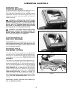
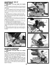
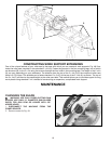
2. Move the table to the 0° straight cut-off position,
making sure the plunger (B) is engaged in the 0° positive
stop and tighten the lock handle (A) as shown in Fig. 27.
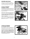
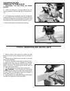
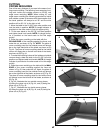
3. Clamp workpiece and make a cut on a piece of
wood, as shown in Fig. 24.
4. Using a square, check to see if the piece of wood
was cut at 90°, as shown in Fig. 25.
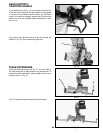
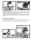
5. If an adjustment is necessary, loosen the lock han-
dle (A) Fig. 26, one turn. Then loosen locknut (B) and
turn eccentric nut (C) right or left as necessary and tight-
en lock nut (B).
6. Make another test cut and if further adjustment is
necessary, repeat the above instructions.
7. When you are certain the cut is at 90°, adjust point-
er (D) Fig. 27, to point to the “0” mark on the scale, by
loosening set screw (E).
8. Once the 90° positive stop is adjusted, all positive
stops will also be adjusted.
A
B
C
D
B
E
A