


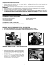
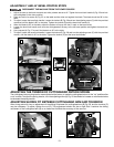
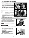

To adjust the sliding fit between the movable table and the base,
turn the nut (A) Fig. 17 clockwise to increase the sliding fit
(opposite to decrease the fit). This adjustment should not be so
tight that it restricts the rotating movement of the table, or so
loose that it affects the accuracy of the saw.
11
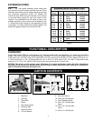
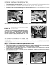
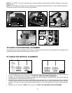
1. This miter saw will cut any angle from 0° to 47° right and left. Turn the locking knob (A) Fig. 15 counter-clockwise, lift the
miter detent trigger (B), and rotate the table.
2. The compound miter saw is equipped with positive stops at 0°, 15°, 22.5°, 30°, and 45° left and right.
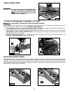
3. The pointer (C) Fig. 16 indicates the actual angle of cut. Each scale line (B) represents 1°. When the center line (C) is moved
from one line to the next on the scale, the angle of the cut is changed by 1°.
ROTATING THE TABLE FOR MITER CUTTING
A
B
C
B
DISCONNECT THE MACHINE FROM THE
POWER SOURCE.
ADJUSTING THE SLIDING FIT BETWEEN THE MOVABLE TABLE AND THE BASE
A
Fig. 15 Fig. 16
Fig. 17
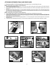
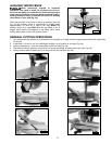
IMPORTANT: Before making this adjustment, set the blade at 0° to the table. See section “ADJUSTING 0° AND 45° BEVEL
POSITIVE STOPS.”
1. Rotate the movable table so that the blade is 90° to the fence and the positive stop is set for 0°.
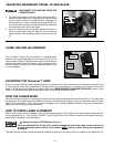
2. Place one end of a square (A) Fig. 18 against the front of the fence (B) (located under the motor), and the other end against
the blade, with the blade locked in the down position. The fence should be 90° to the blade.
3. To adjust the fence (B) Fig. 18, use the supplied wrench to loosen the two screws (C) that attach the fence to the base.
Adjust the fence (B), and tighten the screws (C).
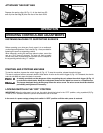
4. Check the opposite fence (D) Fig. 19. To adjust, remove the extension fence, loosen the two screws (E), adjust the fence
(D), and tighten the screws (G).
ADJUSTING THE FENCE 90° TO THE BLADE
DISCONNECT THE MACHINE FROM THE POWER SOURCE.
A
C
B
G
D
Fig. 18
Fig. 19