


13
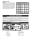
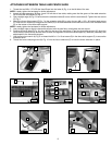
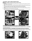
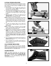
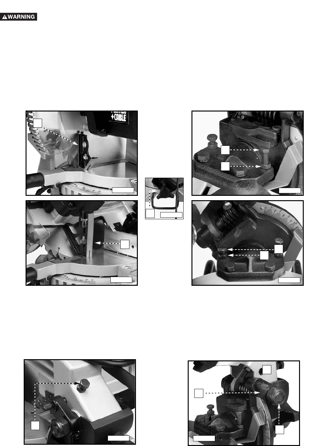
1. Adjust the saw so that both the bevel and miter pointers are set at 0°. Tighten the bevel lock handle (A) Fig. 25 and lock
the cuttinghead in the down position.
2. Place one end of a square (A) Fig. 25 on the table and the other end against the blade. The blade should be 90° to the
table.
3. To adjust, loosen the bevel lock handle. Loosen the locknut (B) Fig. 26 and turn the adjusting screw (C) with the provided
wrenches until the blade is 90° to the table. Tighten the locknut (B) and the bevel lock handle (H).
4. When the blade is 90° to the table, adjust the pointer to line up with the 0° mark on the bevel scale.
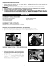
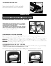
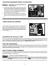
5. Loosen the bevel lock handle, and move the cuttinghead all the way to the left bevel position and tighten the bevel lock
handle.
6. Use a square (A) Fig. 27 to see if the blade is at 45° to the table.
7. To adjust, loosen the bevel lock handle. Loosen the locknut (E) Fig. 28 and turn the adjusting screw (F) with the provided
wrench, until the blade is 45° to the table. Tighten the locknut (E) and the bevel lock handle.
ADJUSTING 0° AND 45° BEVEL POSITIVE STOPS
Fig. 25
Fig. 26
Fig. 28
DISCONNECT THE MACHINE FROM THE POWER SOURCE.
A
B
C
A
Fig. 27
E
F
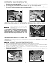
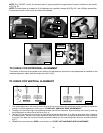
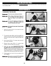
ADJUSTING THE TENSION OF CUTTINGHEAD RETURN SPRING
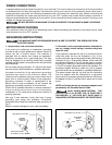
The cuttinghead return spring tension was adjusted at the factory to make the cuttinghead return to the "up" position after
a cut is made. To adjust the spring tension, turn the adjusting screw (A) Fig. 29 clockwise to increase or counterclockwise
to decrease the spring tension.
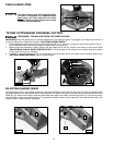
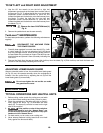
ADJUSTING SLIDING FIT BETWEEN CUTTINGHEAD ARM AND TRUNNION
After a long period of time, an adjustment of the sliding fit between the cuttinghead arm (B) Fig. 30, and the trunnion (C)
may be necessary. To adjust, tighten the nut (D). This adjustment should not be so tight that it restricts the sliding
movement of the cuttinghead arm (B) or so loose that it affects the accuracy of the saw cut.
B
C
D
Fig. 30
Fig. 29
A
Fig. 25A
A