


9
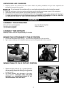
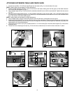
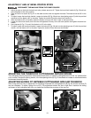
1. Thread the two
M8 x 1.25 x 20 Hex Head Screw
into the holes (A) Fig. 4 on the left side of the saw.
NOTE: Loosely tighten the hardware for further adjustment.
2. Attach the table extension (B) Figs. 4 and 5 to left side of saw table, making sure that the groove of the table extension
(B) is inside the flat washers (C) Fig. 4.
3. Use a straight edge (A) Fig. 6 to ensure that the extension table (B) is even with the saw table (D). Tighten the two screws
(C) Fig. 5.
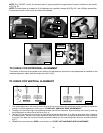
4. Attach the fence slide support (E) Fig. 7 to the extension table (B) by using the two M8 x 1.25 x 30 socket head screws
(F). Insert the two screws up through the two holes (G) in the table extension and thread them into the two threaded holes
(H) on the bottom of the fence slide support.
NOTE: Loosely tighten the hardware for further adjustment.
5. Use a straight edge to align the fence slide support with the saw fence, and tighten the two screws.
6. Position the fence slide (K) Fig. 8 in the valley on the top of the saw fence (J) and the fence slide support (E). Move the
fence slide (K) back and forth several times to check the alignment of the fence slide support (E). Make any necessary final
adjustments to the fence slide support.
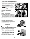
7. Use the 3mm hex wrench (A) Fig. 9 to thread the M6 x 1.0 x 16 set screw (B) in the fence slide support (C) to secure the
extension fence.
8. Thread the fence clamping screw (N) Fig. 10 into the fence extension (E) to hold the fence extension in place.
ATTACHING EXTENSION TABLE AND FENCE SLIDE
A
B
Fig. 4
Fig. 5
B
C
B
E
H
F
Fig. 7
J
E
K
Fig. 8
E
N
Fig. 10
Fig. 6
A
B
D
A
B
C
Fig. 9