


13
Converting from 230 Volt to 460 Volt
(Three Phase Only)
Consult the wiring diagram inside the starter box
cover. A diagram is also included on page 29 of
this manual. The Jointer must comply with all
local and national codes after being wired.
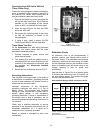
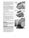
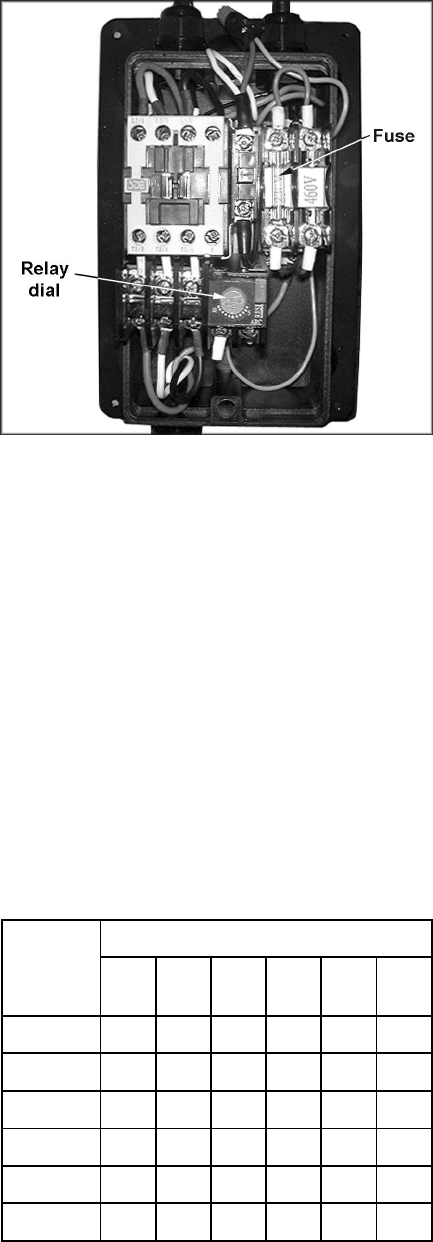
1. Remove the starter box cover and adjust the
dial on the relay (see Figure 12) as close as
possible to the amperage of the Jointer
motor at 460V, as listed on the motor plate.
2. Move the fuse (Figure 12) from the 230V
slot to the 460V slot.
3. Re-connect the incoming leads to the motor
for 460 volt operation, as shown in the
wiring diagram.
4. If using a plug, install a proper UL/CSA
listed plug suitable for 460 volt operation.
Three-Phase Test Run
On the three-phase unit, after wiring has been
completed, you should check that the wires
have been connected properly:
1. Connect machine to power source and
press the start button.
2. The sanding disc and belt should move in
accordance with the arrow directions on the
machine. If the movement is backward, stop
the machine and disconnect machine
from power.
3. Switch any two of the three wires at "R,S,T".
Grounding Instructions
This machine must be grounded. In the event of
a malfunction or breakdown, grounding provides
a path of least resistance for electric current to
reduce the risk of electric shock.
Improper connection of the equipment-
grounding conductor can result in a risk of
electric shock. The conductor with insulation
having an outer surface that is green with or
without yellow stripes, is the equipment-
grounding conductor. If repair or replacement of
the electric cord or plug is necessary, do not
connect the equipment-grounding conductor to a
live terminal.
Check with a qualified electrician or service
personnel if the grounding instructions are not
completely understood, or if in doubt as to
whether the tool is properly grounded.
Repair or replace a damaged or worn cord
immediately.
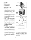
Figure 12
(Three Phase model only)
Extension Cords
An extension cord is not recommended; if
possible, position your Sander within reach of
the power supply. If an extension cord becomes
necessary, make sure the cord rating is suitable
for the amperage listed on the machine’s motor
plate. An undersize cord will cause a drop in line
voltage resulting in loss of power and
overheating.
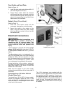
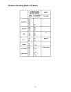
Use the chart in Figure 12a as a general guide
in choosing the correct size cord. If in doubt, use
the next heavier gauge. The smaller the gauge
number, the heavier the cord.
Recommended Gauges (AWG) of Extension Cords
Extension Cord Length *
Amps
25
feet
50
feet
75
feet
100
feet
150
feet
200
feet
< 5 16 16 16 14 12 12
5 to 8 16 16 14 12 10 NR
8 to 12 14 14 12 10 NR NR
12 to 15 12 12 10 10 NR NR
15 to 20 10 10 10 NR NR NR
21 to 30 10 NR NR NR NR NR
*based on limiting the line voltage drop to 5V at 150% of the
rated amperes.
NR: Not Recommended.
Figure 12a