


14
Adjustments
Before putting power to the sander, inspect the
machine thoroughly. Check to ensure that all
screws are tight, all mechanical functions work
freely, belt runs freely and tracks properly, and
the disc runs freely, does not come into contact
with the guard or table, and the abrasive
remains firmly adhered to the sander’s metal
disc.
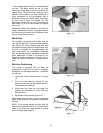
Turn the motor on and check for proper rotation
direction of the belts. The sanding belt should
move from the idler pulley toward the drive
pulley, while the disc should rotate counter-
clockwise with the operator facing the disc.
Arrow labels are affixed to the sander to indicate
these directions.
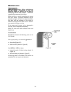
Platen Adjustment
The platen should not require attention on your
new sander. After prolonged use, however, the
platen may occasionally need re-adjustment. To
do this, proceed as follows.
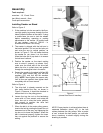
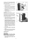
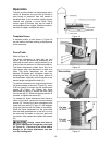
Refer to Figure 13:
1. Swing the end guard out of position and
remove the side cover. Remove the
abrasive belt.
2. Using a 6mm hex wrench, loosen the two
socket head cap screws inside the belt arm
and shift the platen as needed. The platen
should be 1/32” to 1/16” above the tangent
points of the pulleys and in contact with the
belt at both ends. A straight edge can be
used with the abrasive belt to align the
platen, as shown in Figure 13.
3. Re-tighten the socket head cap screws.
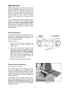
Sanding Table Adjustment
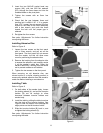
Refer to Figures 14 and 15:
The sanding table may be adjusted from any
angle from 15 degrees up, to 45 degrees down.
To adjust, loosen the locking wheels (A) on both
sides and pivot the table to the desired angle as
shown on the trunnion scale (B). Re-tighten the
locking wheels (A).
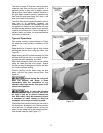
A 45-degree stop (C) is located under the table.
Use an angle measuring device to confirm that
the angle of the table against the stop is 45
degrees. If it is not, adjust by loosening the hex
nut and screwing the stop in or out as needed.
Re-tighten hex nut.
Figure 13
Figure 14