


16
Operation
The belt and disc sander can be equipped with a
variety of abrasives and grit sizes to handle a
wide variety of materials, from soft woods to
hardened steel. It can be used to rapidly remove
material and produce a mirror finish. Using
various types of fixtures, they can be used to
sand template forms, angles, freehand contours,
and flats on edges, surfaces and ends.
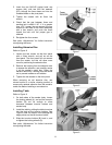
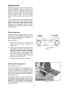
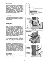
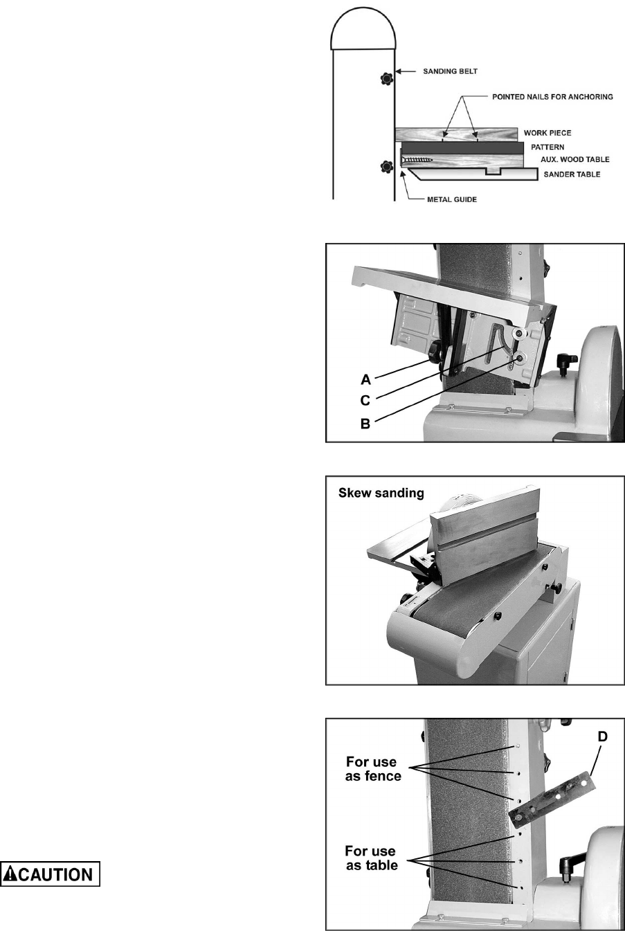
Template Forms
A template similar to that shown in Figure 18
can be made to facilitate sanding multiple pieces
to the same size.
Fence/Table
Refer to Figure 19:
The fence attachment is used with the belt
sander and can be positioned alternately as a
table (with the belt arm in upright position) or as
a fence (with the belt arm in horizontal position).
The fence attachment surface has a slot for a
miter gauge when the attachment is used as a
table. The fence attachment can be tilted
between 90-degree and 45-degree angles by
loosening the knob (A) on the center portion of
the attachment. Manually move the fence to the
desired angle and tighten the knob (A).
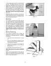
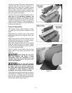
To position the fence at an angle across the belt
(for skew sanding as shown in Figure 20), use a
3/16 hex wrench to loosen the two socket head
screws (B, Figure 19). Rotate the fence
attachment by sliding it around the bolts using
the curved slot (C). When the desired position is
reached, re-tighten the screws (B).
To change the fence attachment from fence to
table, or vice-versa, remove the two socket head
screws (B). Remove the fence attachment and
rotate the pivot plate (D, Figure 21) 180 degrees
lining the holes up with the holes in the sander.
Place the fence attachment on the pivot plate
with the table perpendicular to the belt. Line up
the slots with the holes on the pivot plate and
the sander, then replace and tighten the screws
(B).
Always mount the base of
the fence attachment through the pivot plate
(D, Figure 21). Failure to do so could lead to
damage to the fence attachment and also
ruin the sanding belt.
Figure 18
Figure 19
Figure 20
Figure 21