8
RECEIVING
Open shipping crate and check for shipping damage.
Report any damage immediately to your distributor.
Read the instruction manual thoroughly for assembly,
maintenance and safety instructions.
Contents of crate:
1 planer
1 dust chute w/ hardware
4 special hex head screws w/ hex nuts
4 foot pads w/ hardware
1 knife-setting gauge
1 6mm hex wrench
1 8mm hex wrench
1 10mm hex wrench
1 12mm & 14mm wrench
1 22mm & 24mm wrench
INSTALLATION
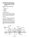
Remove the screws holding the base of the machine to
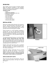
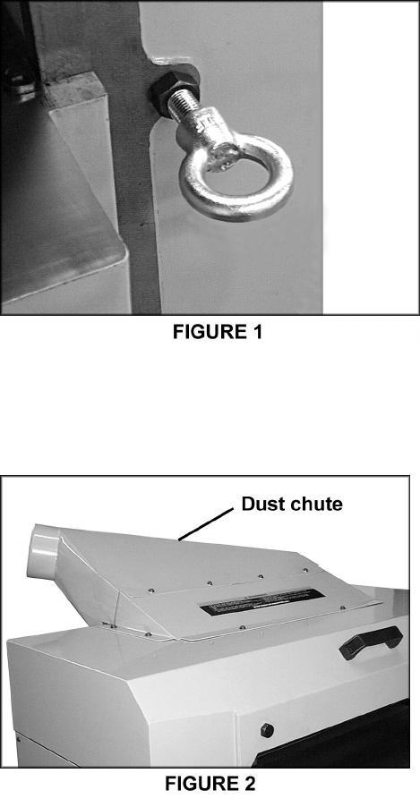
the skid. Use the lifting eyes on front and back of the
planer for hoisting it off the skid. See Figure 1. Make
sure the hex nuts are tightened before lifting. The eyes
should be removed once the planer is situated.
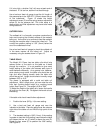
Place the planer on a solid foundation, preferably a
concrete floor. The four foot pads should be placed
beneath the corners and the screws and hex nuts used
for leveling adjustments. Alternately, you can secure the
machine to the floor by using lag screws through the
holes in the base.
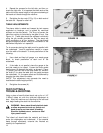
The machine area should be clean, dry, well ventilated,
and well lighted. Since planers can create noise
problems, the site selection should be one which
minimizes reverberant sound from walls, ceilings and
other equipment. Electricals should be installed so that
they are protected from damage and exposure. Be sure
to properly ground the machine frame.
Exposed metal parts have been given a protective
coating at the factory. This should be removed with a
soft rag and kerosene or a good commercial solvent.
Do not use an abrasive pad.
Powermatic strongly recommends that an exhaust
system be used with this machine. It should be of
sufficient volume for this size planer. If an exhaust
system is not used, the user is cautioned against the
health hazard and the limitations in the OSHA regulation
for employee or student exposure to dust particles.
INSTALLING DUST CHUTE
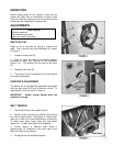
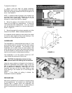
Mount the dust chute with the eight M6 x 10mm hex
screws, eight spring washers, and eight flat washers.
See Figure 2.


