


10
Installation of Panel Saw
Uncrating
Remove the panel saw from the shipping container
and check for damage. Report any damage to the
freight company immediately.
A wooden block and three cables have been
fastened to the counterweight to secure it during
shipment. This wooden block and cables must be
removed before operation of the saw. Follow steps
1 through 4:
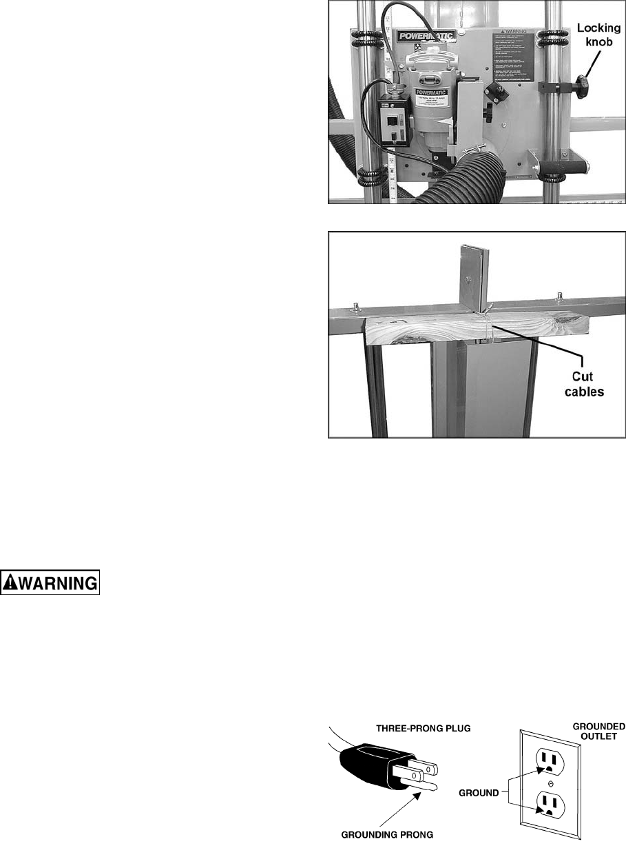
1. Make sure the cable attached to the motor
carriage is placed over the pulley on top of the
panel saw.
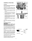
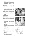
2. Loosen the locking knob on the motor carriage
and move the carriage down to the bottom of
the panel saw. See Figure 3. Tighten the
locking knob securely.
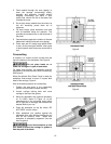
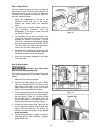
3. At the back of the panel saw, on top of the
counterweight housing, lift up on the wood
block and cut the cables attached to the block.
See Figure 4. DO NOT cut the main cable that
runs through the pulley.
4. Remove the cables and wood block so that the
counterweight can slide freely inside the
housing.
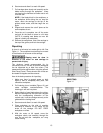
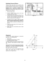
Make sure there is enough space on both sides of
the panel saw for loading, passing, and off-loading
panels.
Grounding Instructions
Improper connection of the
grounding wire can result in electric shock. If
you are unsure whether an outlet is properly
grounded, consult a qualified electrician.
Do not modify the plug provided with the saw and
never remove the grounding prong from the plug. If
cord or plug is damaged, have it repaired before
using the machine. If plug will not fit the outlet,
have a proper outlet installed by a qualified
electrician.
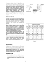
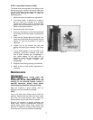
The plug must be connected to a properly
grounded outlet, shown in Figure 5, grounded and
installed in accordance with all codes and
ordinances. If the machine should electrically
malfunction or break down, grounding provides a
path of least-resistance to carry electricity away
from the operator, reducing risk of electric shock.
The grounding prong on the plug is connected
through the green wire inside the cord to the
grounding system in the machine.
The green wire must be the only wire connected to
the machine’s grounding system and must never
be attached to an electrically “live” terminal.
Figure 3
Figure 4
Figure 5