


16
Step 1: Align Rollers
The two outermost rollers are fixed, so adjust all
other rollers to them. Place the 6-foot edge of the
square across the rollers to check for alignment.
The edge of the square should touch all rollers. If it
does not, adjust as follows:
1. Clamp the straightedge to the top of the
outermost rollers and flat to the frame.
Position the clamps above the outermost
rollers.
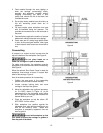
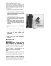
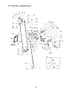
2. Turn each roller to ensure it does not jam or
have excessive clearance from the
straightedge. If this occurs, loosen the roller
nut, shown in Figure 18.
3. The adjustable rollers have an eccentric hub.
Turning the roller when the roller nut is loose
changes the position of the roller. Turn the
roller until it touches the straightedge, making
sure the straightedge does not bend. NOTE:
The roller panel may have to be loosened in
order to turn the roller. See Figure 18.
4. When the roller is positioned, tighten the roller
nut. NOTE: If a fixed roller has been replaced,
the above procedure should be repeated.
5. Leave the test square clamped to the rollers
for the next step.
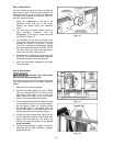
Step 2: Align Guides
Disconnect saw from power
source before aligning the guides.
If the saw does not cut at 90 degrees, the guides
may not be perpendicular to the rollers. Adjust as
follows:
1. Make sure the rollers are aligned.
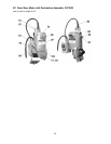
2. Remove the blade guard and mark a blade
tooth as a reference (NOTE: If the saw has a
high speed steel blade, mark a tooth that
points toward the edge of your test square,
which is still clamped above the rollers.)
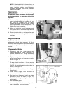
3. Pull the carriage down until the reference tooth
of the blade just touches the vertical edge of
the test square, Figure 19. Continue pulling
the carriage down; if the blade does not
contact the square, or the blade binds on the
square, the guides are not aligned properly.
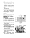
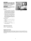
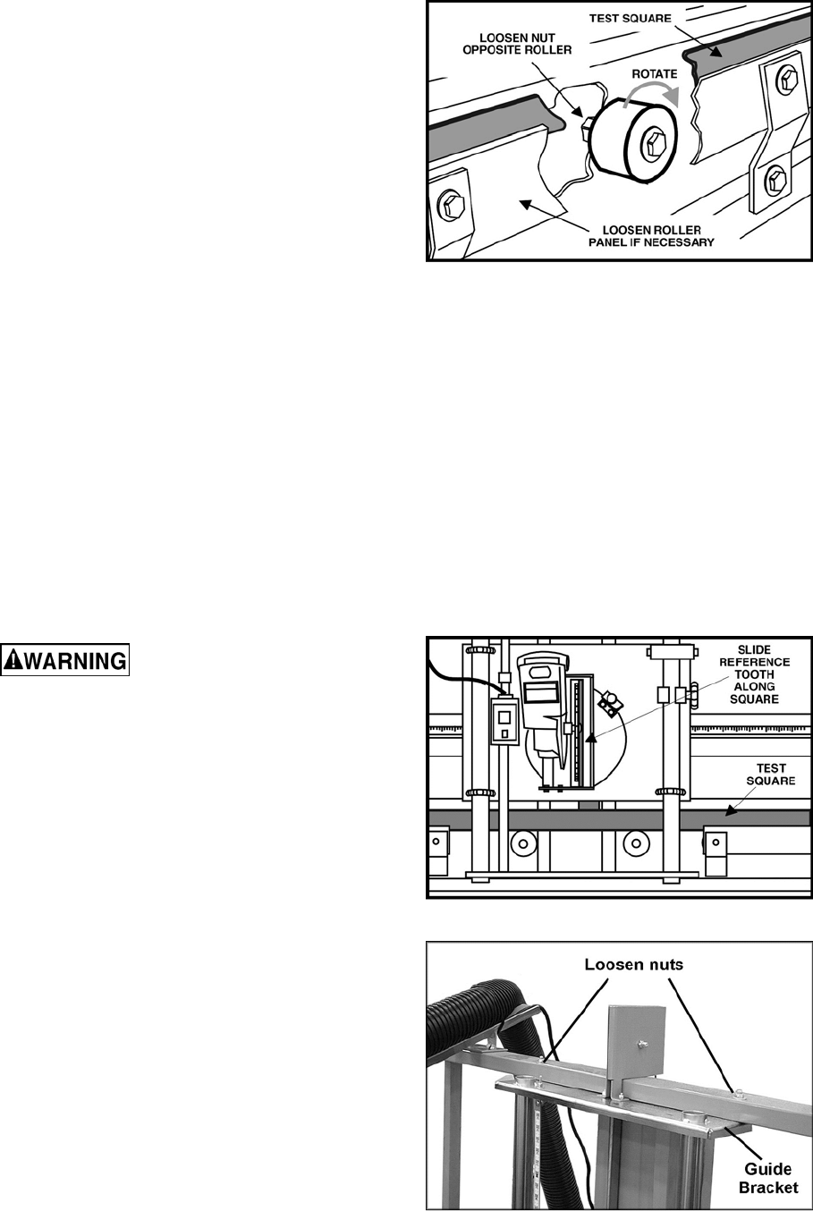
4. Loosen the guide bracket nuts, Figure 20, but
do not remove the bracket. With a dead blow
mallet, strike the bracket on the side in the
direction you want the guides to go. Do not
strike the guides.
5. Confirm the squareness of guides to rollers as
described above. When satisfied, re-tighten
guide bracket nuts.
Figure 18
Figure 19
Figure 20