


11
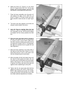
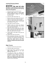
6. Attach the fence (D, Figure 2) to the fence
body (E, Figure 2) with four 5/16 x 3/4 hex cap
screws, four 5/16 lock washers, and four 5/16
flat washers. Hand tighten the screws only.
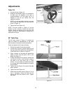
7. Place the fence assembly onto the guide rail
and against the edge of the miter slot, as
shown in Figure 2. The hook at the rear of the
fence should fit under the rear rail (see Figure
5).
8. The fence must align parallel to the miter slot
along the entire length of the fence.
9. Lock the fence by pushing down the lock
handle (G, Figure 2). Because the screws are
only hand-tight, you can shift the fence slightly
as needed until the fence parallels the miter
slot.
10. When the fence has been properly aligned to
the miter slot, tighten the four hex cap screws
(F, Figure 2) with a 12mm wrench. Make sure
the fence remains parallel to the miter slot as
you tighten the screws. (NOTE: This alignment
will again be checked once the guide rail has
been tightened.)
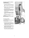
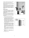
11. Move the fence assembly to the other side of
the blade so that the pointer (Figure 3) on the
fence body points to “zero” on the scale. Lock
the fence by pushing the handle down.
12. Move the guide rail with the locked fence until
the fence is flush against the blade. (Do not
force the fence into the blade so that the blade
bends.) See Figure 3. Do not unlock the fence
to perform this. Move the fence and guide rail
together when establishing the zero point.
13. Tighten the five hex cap screws that hold the
guide rail to the front rail, with a 10mm wrench.
NOTE: After tightening the guide rail, double
check that the fence is still parallel to the miter
slot. Make additional adjustments if needed.
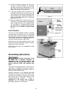
Figure 2
Figure 3