


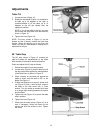
18
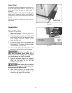
Upper Blade Guide Assembly
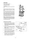
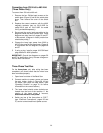
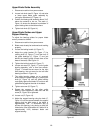
1. Disconnect machine from power source.
2. Loosen lock knob (see B, Figure 14) and raise
or lower upper blade guide assembly by
turning the handwheel (C, Figure 14).
3. Position the blade guide assembly about 3/16”
above the material to be cut. The scale (J,
Figure 14) shows the distance from bottom of
upper blade guides to the table surface.
4. Tighten lock knob (B, Figure 14).
Upper Blade Guides and Upper
Support Bearing
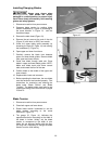
To adjust the bearing guides for proper blade
control, proceed as follows.
1. Disconnect machine from power source.
2. Blade must already be tensioned and tracking
properly.
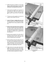
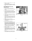
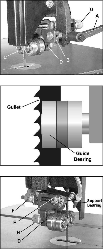
3. Loosen the locking handle (A, Figure 17).
4. Adjust the guide bracket (B, Figure 17) by
rotating knob (G, Figure 17) until the front of
the guide bearings (C, Figure 17) are just
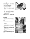
behind the blade’s gullet (curved area at the
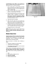
base of the tooth). See Figure 18.
5. Tighten the locking handle (A, Figure 17).
6. Loosen set screw (D, Figure 17) on the guide
bearing assembly, with a 3mm hex wrench.
(Figure 17 shows the set screw for the right
hand bearing; the set screw for the left hand
bearing is shown in Figure 19.)
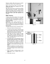
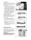
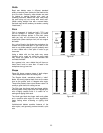
7. The guide bearing rotates on an eccentric
shaft. Adjust the guide bearing, by rotating the
knob (H, Figure 19) until the guide bearing
rests lightly against the blade. Do not force the
guide bearing against the side of the blade.
8. Tighten set screw (D, Figure 17).
9. Repeat the process for the other guide
bearing. After adjustment, make sure the set
screw (D, Figure 19) is tightened.
10. Loosen nut (E, Figure 19).
11. Adjust the support bearing using the knob (F,
Figure 19) until the space between the support
bearing and the back edge of the blade is
approximately 1/64”. A convenient way to
achieve this spacing is by placing a dollar bill
folded twice (four thicknesses of a dollar bill is
approximately 1/64”) between blade and
support bearing.
Figure 17
Figure 18
Figure 19