


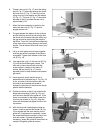

22
4. Tighten wing nut (D, Fig. 25) after blade is
tracking in the center of the wheel.
5. Close upper wheel guard.
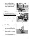
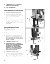
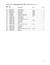
Adjusting Upper Blade Guide Assembly
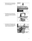
1. Disconnect machine from power source.
2. Loosen lock knob (A, Fig. 26) and raise or
lower upper blade guide assembly (B, Fig. 26)
to just above the material being cut.
3. Tighten lock knob.
4. The upper blade guide is spring loaded. To
adjust the tension on the spring, remove knob
(A, Fig. 26), tighten or loosen set screw (C,
Fig. 26) until desired tension is reached, then
replace knob.
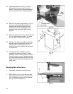
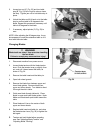
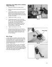
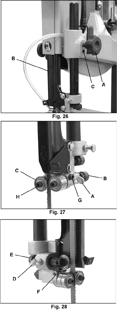
Adjusting Upper Blade Guide &
Blade Support Bearing
1. Disconnect machine from power source.
2. Blade must already be tensioned and tracking
properly.
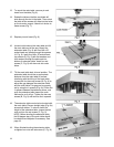
3. Loosen thumb screw (A, Fig. 27) and move
guide block by turning knob (B, Fig. 27) so
that the front of the guide wheels (C, Fig. 27)
are just behind the gullet (curved area at base
of tooth) of the blade.
4. Tighten thumb screw (A, Fig. 27).
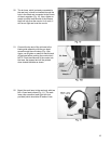
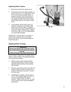
5. Loosen thumb screw (D, Fig. 28) and turn
knob (E, Fig. 28) to move the support bearing
(F, Fig. 28) in or out until the bearing is
approximately 1/64" behind the blade. A
simple way to set this distance is to place a
piece of paper or a dollar bill between the
support bearing and the blade.
6. Tighten thumb screw (D, Fig. 28).
7. Loosen the cap screw (G, Fig. 27) and turn
the screw on each guide wheel (H, Fig. 27) to
move the guide wheels 1/64” from the blade.
Tighten cap screw (G, Fig. 27) when finished.