


10
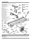
ASSEMBLY
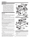
WARNING:
The saw mounting brackets are designed to fit
snugly over the table edges with locking levers in
the open position. With the locking levers in the
lowered (locked) position, you should not be able
to slide the saw mounting bracket assembly along
the table edges or remove the bracket assembly
from the table edges. If the saw mounting brackets
will not fit over the edges, or if the brackets can
be removed from the edges when the levers are
locked, remove bracket assembly immediately
and adjust bracket adjustment screw. See the
Maintenance section of this manual. Failure to heed
this warning may result in serious personal injury.
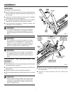
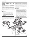
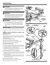
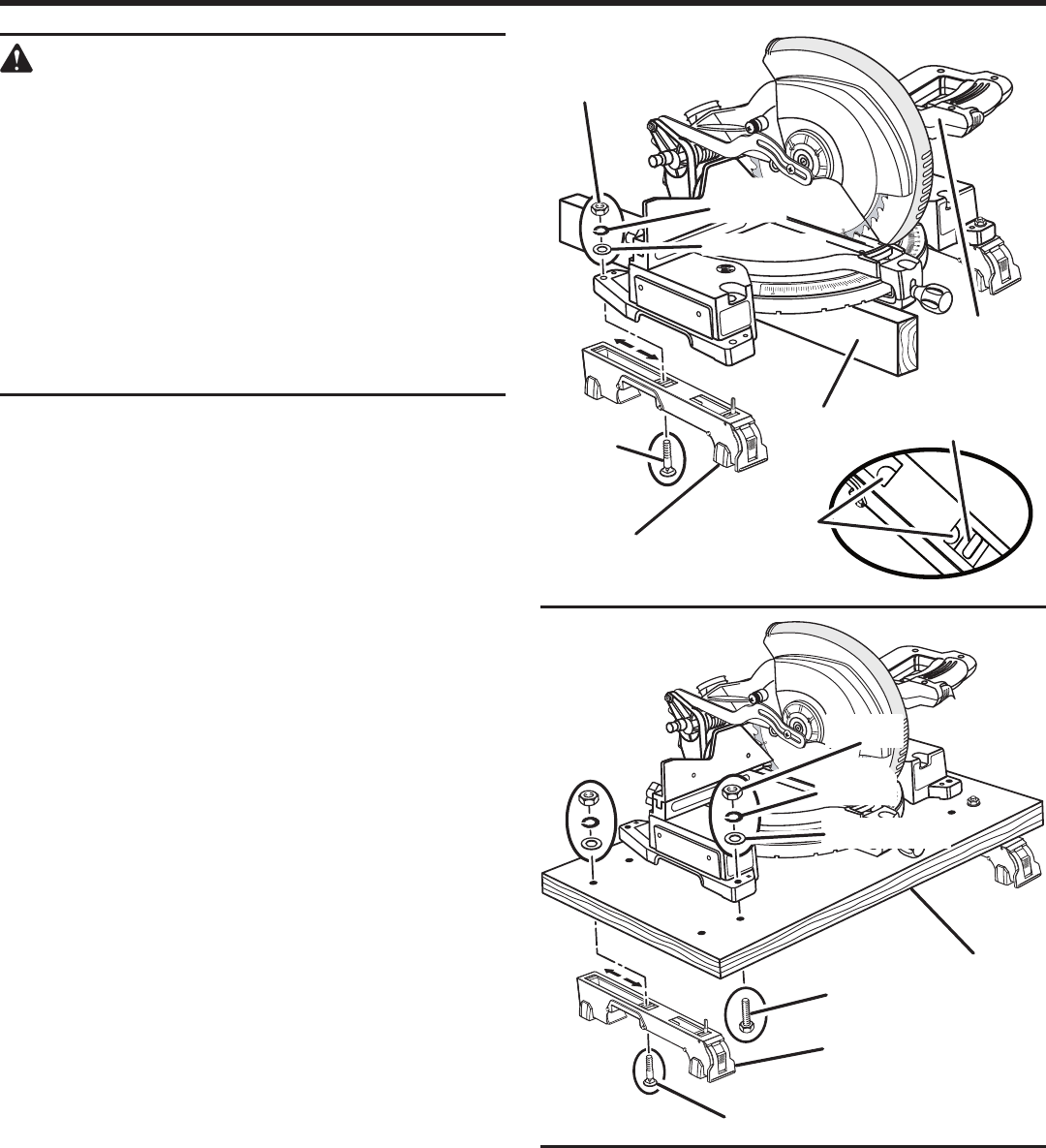
ATTACHING SAW TO THE MOUNTING
BRACKETS
See Figures 11 - 12.
Always position the saw to achieve maximum balance and
stability. All four corners of the saw must be bolted to the
mounting brackets before use. Make sure bolts do not
extend above the table of the miter saw.
NOTE: Four additional 1-1/2 in. bolts have been provided
for use when securing a sliding miter saw to the mounting
brackets.
NOTE: Ensure that mounting brackets can be clamped
securely onto stand before mounting saw. If locking lever on
saw mounting bracket cannot easily be pushed down into
the closed position, the adjustment screw is too tight. Do
not force locking lever into the closed position. Loosen the
adjustment screw. Refer to the Maintenance section later in
this manual for mounting bracket adjustment.
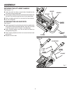
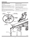
If the saw has mounting holes that line up with the slots
in the saw mounting brackets:
Disconnect the saw from power supply and lock the saw
arm in the down position.
Place a 2 x 4 or similar type of stable support underneath
the saw to raise the saw and allow access to the saw’s
mounting feet.
Feed a carriage bolt up through each side of the bracket
and adjustment plate.
Align bolts in the two sliding adjustment plates on the
saw mounting bracket with the saw mounting holes.
Place the saw mounting bracket underneath the raised
side of the saw, and insert bolts through mounting holes
in saw.
Loosely secure in place using a flat washer, lock washer,
and hex nut.
Repeat procedure to attach second bracket to saw.
After making sure both brackets are parallel to each other,
lightly tighten all four nuts to hold in position.
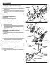
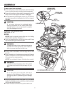
If the saw has holes that do not line up with the sliding
adjustment plates in the saw mounting brackets:
Fig. 12
15
20
25
30
35
40
45
10
HEX BOLT
CARRIAGE BOLT
MOUNTING
SURFACE
HEX NUT
FLAT WASHER
LOCK
WASHER
SAW
MOUNTING
BRACKET
Disconnect the saw from power supply and lock saw arm
in the down position.
Mount the saw to a mounting surface at least 1/2 in.
thick using 5/16 hex head bolts, washers, and nuts (not
included).
Drill holes in the mounting surface to match the sliding
adjustment plates in the saw mounting brackets.
Proceed with installation as previously described.
15
20
25
30
35
40
45
10
CARRIAGE
BOLT
SAW
MOUNTING BRACKET
HEX NUT
STABLE
SUPPORT
SLIDING
ADJUSTMENT
PLATE
Fig. 11
FLAT WASHER
SAW ARM
CARRIAGE BOLT
LOADING SLOTS
LOCK
WASHER