


13
0
0
2
4
50
100
150
230
200
bar
100
0
0
16
5
50
150
200
230
bar
psi
TM
2
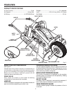
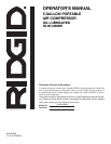
MINI WHEELBARROW COMPRESSOR
OIL LUBE PUMP
-
POMPE A HULE - BOMBA CON LUBRICACION DE AC
IETE
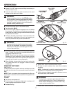
Attach 1/4 in. NPT male connector fitting to accessory or
tool you intend to use.
Insert the other end of the male connector to the quick
coupler on the open end of hose.
WARNING:
Always ensure the switch is in the OFF (O) position
and the regulator pressure gauge reads zero before
changing air tools or disconnecting the hose
from the air outlet. Failure to do so could result in
possible serious personal injury.
Connect the power cord to the power supply.
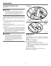
Turn the switch ON ( l ).
Pull out and rotate pressure regulator knob to desired
line pressure. Turning the knob clockwise increases air
pressure at the outlet; turning counterclockwise reduces
air pressure at the outlet.
Following all safety precautions in this manual and the
manufacturer’s instructions in the air tool manual, you
may now proceed to use your air-powered tool.
WARNING:
Air powered tools may require more air consumption
than this air compressor is capable of providing.
Check the tool manual to avoid damage to the tool
or risk of personal injury.
Control the amount of air flow with the pressure regulator
knob. Turning the knob fully counterclockwise will
completely stop the flow of air.
NOTE: Always use the minimum amount of pressure
necessary for your application. Using a higher pressure
than needed will drain air from the tank more rapidly and
cause the unit to cycle on more frequently.
When finished, always drain the tank and unplug the
unit. Never leave the unit plugged in and/or running
unattended.
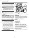
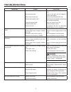
DRAINING THE TANKS
See Figure 11.
To help prevent tank corrosion and keep moisture out of the
air used, the air tanks of the compressor should be drained
daily.
NOTE: The air compressor has two separate tanks. Be sure
to open drain valves for both and perform this operation for
both tanks.
To drain:
Turn the air compressor off.
Pull the ring on the pressure relief valve to release until
pressure gauge reads less than 20 psi.
Release the ring.
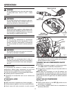
Fig. 10
TANK
PRESSURE GAUGE
OPERATION
Fig. 11
TANK DRAIN
VALVES (2)
PRESSURE
REGULATOR KNOB
TO OPEN
TO
CLOSE
QUICK-CONNECT
AIR FITTING
1/4 in. QUICK
COUPLER
Fig. 9
OFF
ON
OFF
ON
REGULATOR
PRESSURE GAUGE
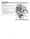
Rotate drain valves counterclockwise to open.
Tilt tank to drain moisture from tank into a suitable
container.
NOTE: Condensate is a polluting material and should be
disposed of in compliance with local regulations.
If drain valves are clogged, release all air pressure, remove
and clean valves, then reinstall.
WARNING:
Unplug the air compressor and release all air from
the tanks before servicing. Failure to depressurize
tanks before attempting to remove valve may
cause serious personal injury.
Rotate drain valves clockwise until tightly closed.