


22
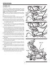
SCALE
INDICATOR
INDICATOR
SCREW
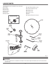
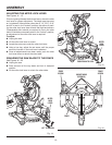
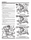
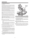
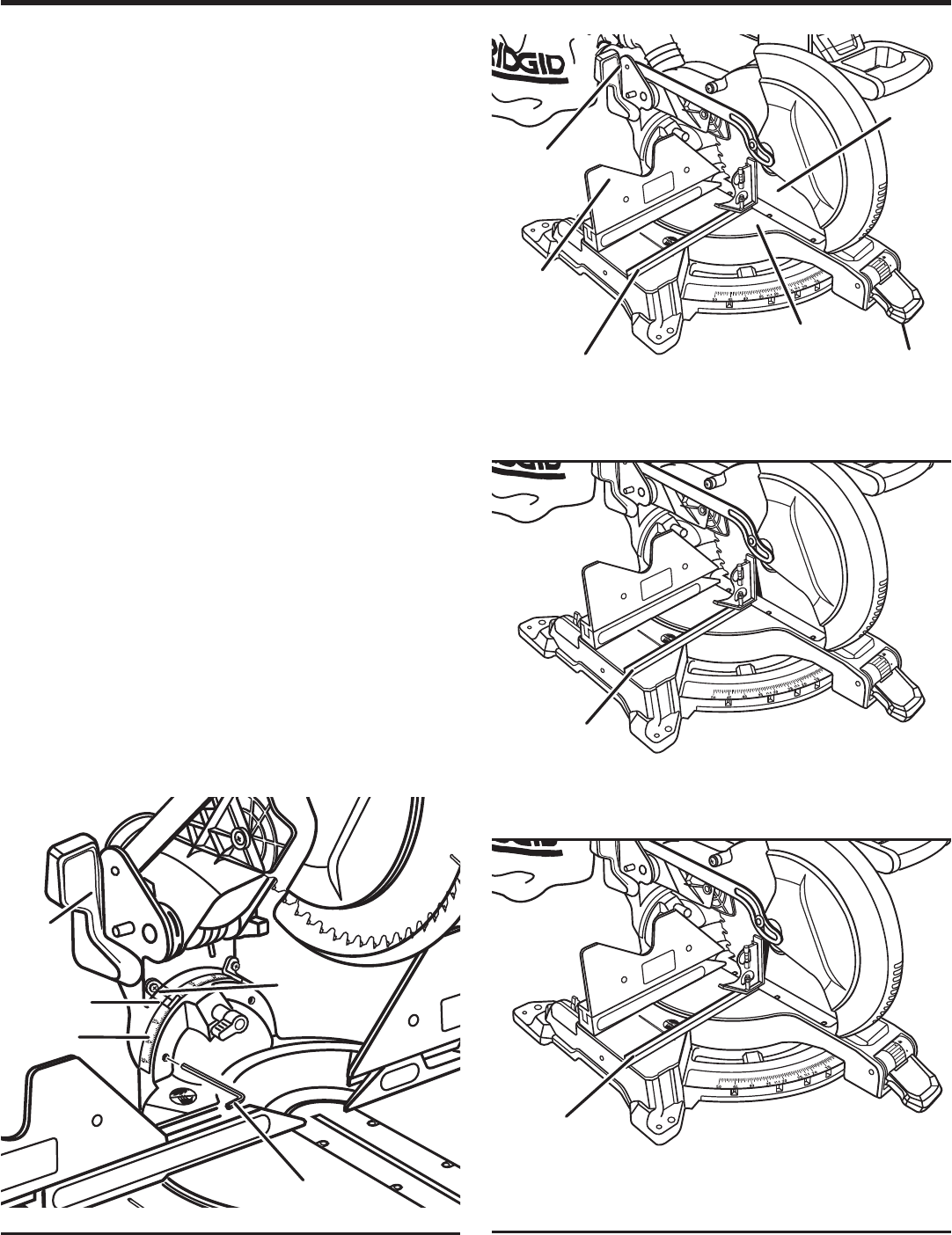
SQUARING THE BLADE TO THE MITER TABLE
See Figures 24 - 27.
Unplug the saw.
Pull the saw arm all the way down and lock in transport
position.
Lift the miter lock lever to unlock. Rotate the miter table
and set the saw at 0
°
miter.
NOTE: The miter table will seat itself in the index point.
Lock the miter lock lever by pushing it down.
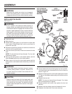
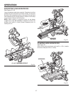
Pull the bevel lock lever forward to unlock and set the saw
at 0
°
bevel (blade set 90
°
to miter table and locked in bevel
index point). Push the bevel lock lever back to relock.
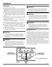
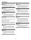
Place a combination square against the miter table and
the flat part of saw blade.
NOTE: Make sure that the square contacts the flat part
of the saw blade, not the blade teeth.
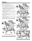
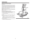
Rotate the blade by hand and check the blade-to-table
alignment at several points.
The edge of the square and the saw blade should be
parallel as shown in figure 25.
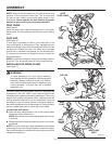
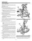
If the top or bottom of the saw blade angles away from
the square as shown in figures 26 and 27, adjustments
are needed.
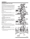
Using a hex key, loosen the two screws inside the pivot
assembly. See Figure 24. Move the saw head as needed
to bring the saw blade into alignment with the square.
Retighten the screws.
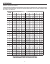
NOTE: The above procedure can be used to check blade
squareness of the saw blade to the miter table at both 0
°
and 45
°
angles.
Your saw has several scale indicators. After squaring adjust-
ments have been made, it may be necessary to loosen the
indicator screws and reset them to zero.
CORRECT VIEW OF BLADE
SQUARE WITH MITER TABLE
VIEW OF BLADE NOT SQUARE WITH MITER TABLE,
ADJUSTMENTS ARE REQUIRED
Fig. 27
VIEW OF BLADE NOT SQUARE WITH MITER TABLE,
ADJUSTMENTS ARE REQUIRED
Fig. 25
ASSEMBLY
BEVEL
LOCK
LEVER
SLIDING
MITER
FENCE
COMBINATION
SQUARE
MITER
TABLE
MITER
LOCK
LEVER
BLADE
COMBINATION
SQUARE
Fig. 26
Fig. 24
COMBINATION
SQUARE
BEVEL
SCALE
BEVEL
LOCK
LEVER
HEX KEY