


25
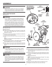
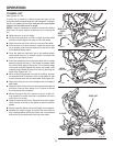
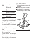
TO BEVEL CUT
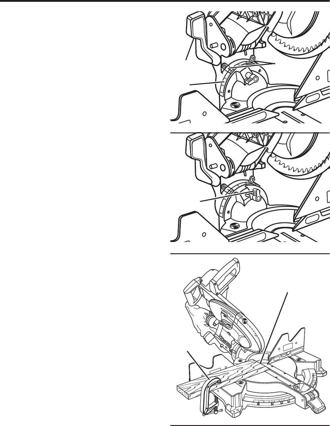
See Figures 30 - 32.
A bevel cut is made by cutting across the grain of the
workpiece with the blade angled to the workpiece. A straight
bevel cut is made with the miter table set at the zero degree
position and the blade set at an angle.
NOTE: It may be necessary to adjust or remove the sliding
miter fence to insure proper clearance prior to making the
cut.
Raise saw arm to its full height.
Lift the miter lock lever to unlock. Rotate the miter table
until the pointer aligns with zero on the miter scale.
Push the miter lock lever down to lock the miter table.
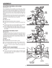
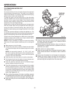
Pull the bevel lock lever forward, rotate the bevel stop
pin to release, and move the saw arm to the left or right
to the desired bevel angle.
Once the saw arm has been set at the desired angle,
rotate bevel stop pin to locked position, and push the
bevel lock lever back to lock.
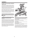
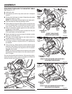
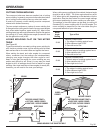
Place the workpiece flat on the miter table with one edge
securely against the fence. If the board is warped, place
the convex side against the fence. If the concave edge
of a board is placed against the fence, the board could
collapse on the blade at the end of the cut, jamming the
blade. See Figures 40 - 41.
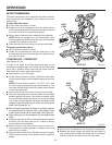
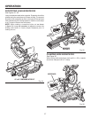
When cutting long pieces of lumber or molding, support
the opposite end of the stock with a roller stand or with
a work surface level with the saw table. See Figure 35.
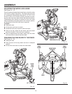
Align the cutting line on the workpiece with the edge of
saw blade.
Grasp the stock firmly with one hand and secure it against
the fence. Use the work clamp or a C-clamp to secure
the workpiece when possible.
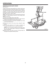
Before turning on the saw, perform a dry run of the cut-
ting operation to make sure that no problems will occur
when the cut is made.
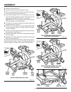
Grasp the saw handle firmly. Squeeze the switch trigger.
Allow several seconds for the blade to reach maximum
speed.
Slowly lower the blade into and through the workpiece.
Release the switch trigger and allow the saw blade to
stop rotating before raising the blade out of workpiece
and removing the workpiece from the miter table.
Fig. 32
Fig. 30
Fig. 31
OPERATION
BEVEL
STOP PIN
BEVEL
SCALE
SCALE
INDICATOR
C-CLAMP
BEVEL CUT
BEVEL LOCK
LEVER