


INSTALLATION
CRYSTALVIEW PRO FIBER
INSTALLATION AND OPERATIONS MANUAL
15
Installation
Please refer to the safety section first before proceeding with any
installation or configuration of the CrystalView Pro Fiber.
NOTE: If your CPU uses a DVI video card and the KVM station’s monitor
is a TFT (flat panel) DVI monitor, pixelclock and phase adjustments
should not be needed. Refer to the set-up section for mixed VGA and DVI
equipment installation. The CrystalView Pro Fiber’s design does not
support plug & play on the local KVM access models.
When installing the CrystalView Pro Fiber, locate the transmitter as close
as possible to the CPU or switch. Keep the CPU cables as short as
possible but still give some freedom of movement. Using shorter VGA
cables keeps the video noise to a minimum and reduces installation costs.
You can mount the CrystalView Pro Fiber in a CPU rack with the optional
rack mount kit. When mounting the units in a rack, follow the instructions
in Appendix D and Appendix E. Provide adequate air circulation to assure
that the maximum operating temperature is not exceeded.
Wherever the transmitter and receiver units are located, they should be on
a secure surface and free from obstructions and objects that may cause
damage to the units.
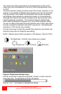
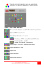
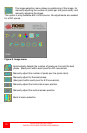
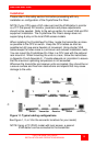
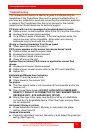
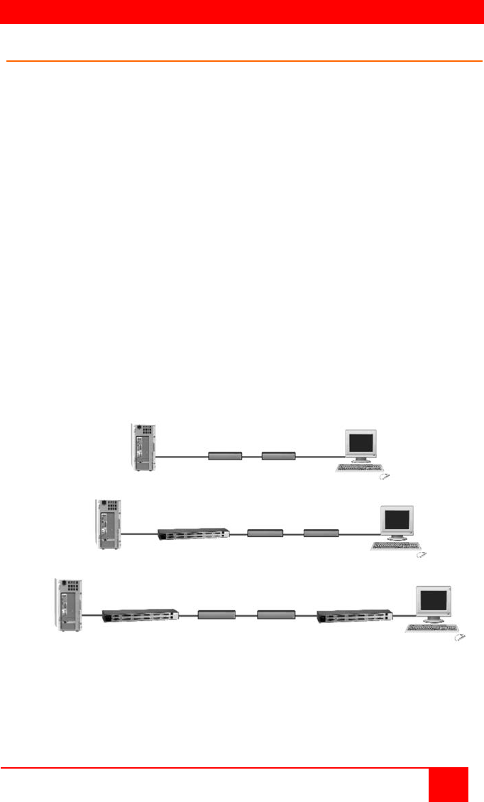
Figure 11. Typical cabling configurations
See Figure 1, 2, or 3 for the connector locations for your model)
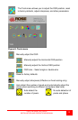
NOTE: Using a PC (PS/2) model with local access, a second
KVM station can be connected to the transmitter.
A
B
C
1 2 3
Transmitter Receiver
Switch Transmitter Receiver
Switch Transmitter Receiver Switch
1 2 3 4
1 2 3 4 5